00195941-03-UM SiplaceCA-EN.pdf - 第367页
User Manual SIPLACE CA 5 Tasks on the Machine Edition 08/2011 EN 5.10 Refilling Components at the Changeover Table 367 5.10 Refilling Component s at the Changeover T able The online help cont ains information on refillin…
5 Tasks on the Machine User Manual SIPLACE CA
5.9 Avoiding Track Errors Edition 08/2011 EN
366
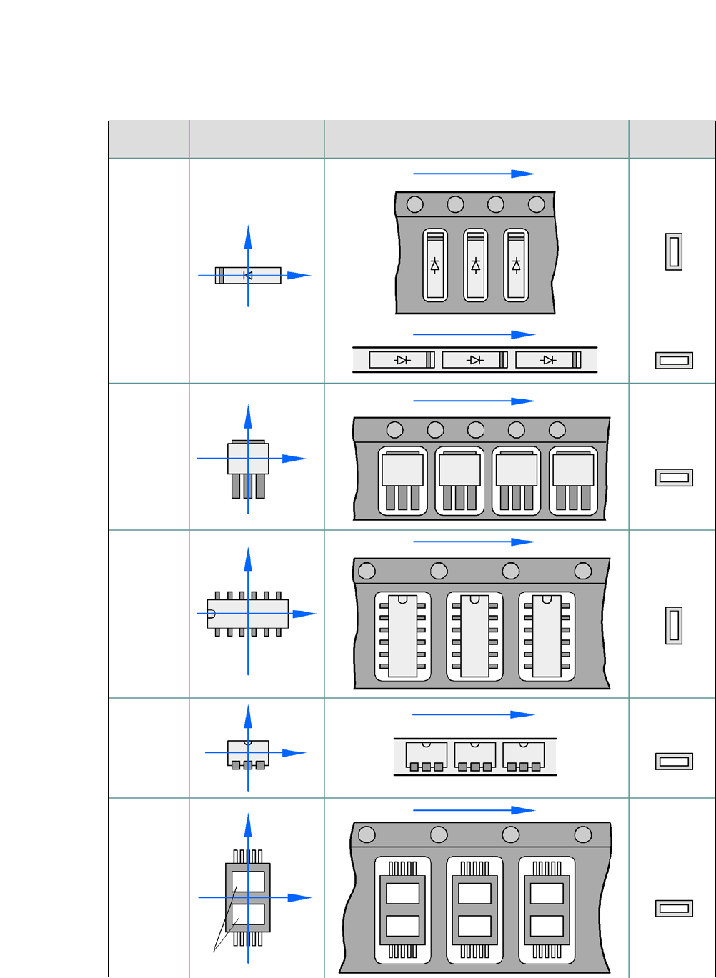
5.9.2 Component Coordinate System and Pickup Angle
5
Fig. 5.9 - 1 Position of the component and its pickup angle
Special
component
Stick
magazine:
Chip-
components
with polarity
0402
2220
The anode must be
aligned with the +X
coordinate.
Package form Coordinate system
Position in the feeder module
Pickup angle/
nozzle angle
Tape:
SOT 23
Stick
magazine:
Tape:
Tape:
SO-IC
DIL-IC
SOT 194
Tape:
Holes
Y
X
Y
X
Y
X
Y
X
Y
X
90°
90°
0°
90°
-90°
0°

User Manual SIPLACE CA 5 Tasks on the Machine
Edition 08/2011 EN 5.10 Refilling Components at the Changeover Table
367
5.10 Refilling Components at the Changeover Table
The online help contains information on refilling components with and without barcodes.
When using tape feeders, make sure that you always splice on a new tape in good time, so
that the feeders do not run empty.
However, do not splice the tapes too early because if you wind the tape onto the new reel
after splicing the end of the old tape, the reel with the new tape may be overfilled. The tape
could then slip off the reel and become tangled. Under certain circumstances, this could
cause pickup errors and prolonged down times.
When using tape reels of 15" (381 mm) and higher, always use spindles (see fig. 5.4 - 4) and
make sure that the partition plates are inserted correctly (see fig. 5.4 - 3
).
5.11 Refilling Components at the SWS with Wafer
Changer System
When all wafers of one die type have been processed, (note on the user interface ) remove
the magazine from the magazine lift and replace the processed wafer.
Alternatively an entire processed wafer magazine can also be replaced by a further, already
prepared magazine with new wafers.
5 Tasks on the Machine User Manual SIPLACE CA
5.12 Docking the Component Trolley In or Out Edition 08/2011 EN
368
5.12 Docking the Component Trolley In or Out
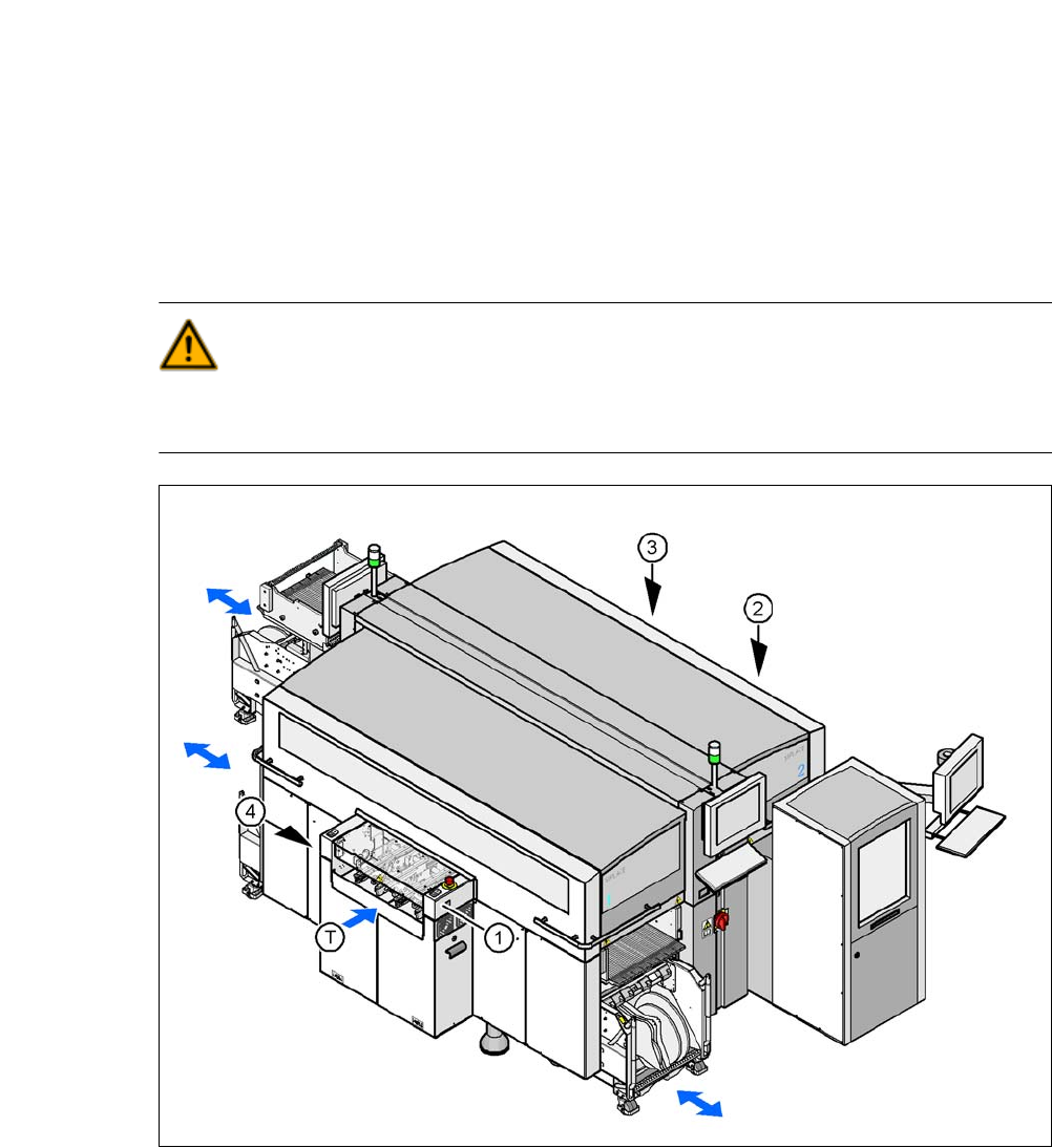
5.12.1 Safety Instructions for Docking Component Trolleys In and Out
WARNING 5
To prevent accidents (risk of crushing), the component trolley may only be docked in or out by
one person.
5
Fig. 5.12 - 1 Safety instructions for docking the component trolley in or out
(1) Button for docking the component trolley in or out, location 1
(2) Button for docking and undocking the component trolley, location 2 (without function here, as
the location is occupied with an SWS)
(3) Button for docking the component trolley in or out, location 3
(4) Button for docking the component trolley in or out, location 4
(T) Direction of PCB transport