00195941-03-UM SiplaceCA-EN.pdf - 第303页
User Manual SIPLACE CA 4 Setting Up and Commissioning Edition 08/2011 EN 4.5 Setting Up the Placement Machine 303 4.5.1 1.5 Fitting the Side Plates Fasten the ground cab le to each sid e plate (ite m 6 in fig. 4.5 - 15…

4 Setting Up and Commissioning User Manual SIPLACE CA
4.5 Setting Up the Placement Machine Edition 08/2011 EN
302
4.5.11.3 Box-PC Slide In of the CA4 and CA3- Plug In Connectors at the Rear
4
4
4.5.11.4 Installing the Box PC Unit
Connect the plug-in connectors at the rear of the PC unit (see section 4.5.11.3).
Carefully lift the box PC unit onto the rail in the extension kit.
Make sure that you do not squash any cables.
Push the box PC unit into the extension kit as far as the stop.
Connect the plug-in connectors at the front of the PC unit (see section 4.5.11.2).
Fix the cables to the front panel with cable ties.
Secure the box PC unit with the fillister head screw.
Fasten the ground cable to the door (item 2 in fig. 4.5 - 15, page 293), as shown in fig. 4.5 -
17 on page 297.
Lock the doors.
NOTE 4
In case of CA4- and CA3 machines continue with paragraph 4.5.13
"Install Axis Slide In at the
CA4 and CA3" on page 309.
Box PC unit, rear
side
(fig. 4.5 - 20
)
plugs
Connection cable NOTE
Plug Cable
PE1 Cable ring Grounding cable
Fasten as in fig. 4.5 - 17
, page
297
X1rz X1rz 03051757 Insert as far as the stop
X3rz X3rz 03050907 Insert as far as the stop
X1pd X1pd 03051751 Insert as far as the stop
X2pd X2pd 03051752 Insert as far as the stop
X3pd X3pd 03051753 Insert as far as the stop
X4pd X4pd 03051754 Insert as far as the stop

User Manual SIPLACE CA 4 Setting Up and Commissioning
Edition 08/2011 EN 4.5 Setting Up the Placement Machine
303
4.5.11.5 Fitting the Side Plates
Fasten the ground cable to each side plate (item 6 in fig. 4.5 - 15, page 293), as shown in fig.
4.5 - 17
, page 297.
Fix the side plate to the machine frame with 6 fillister head screws.
Continue with section 4.5.14 "Fitting the Main Fault Indicator", page 311.
4 Setting Up and Commissioning User Manual SIPLACE CA
4.5 Setting Up the Placement Machine Edition 08/2011 EN
304
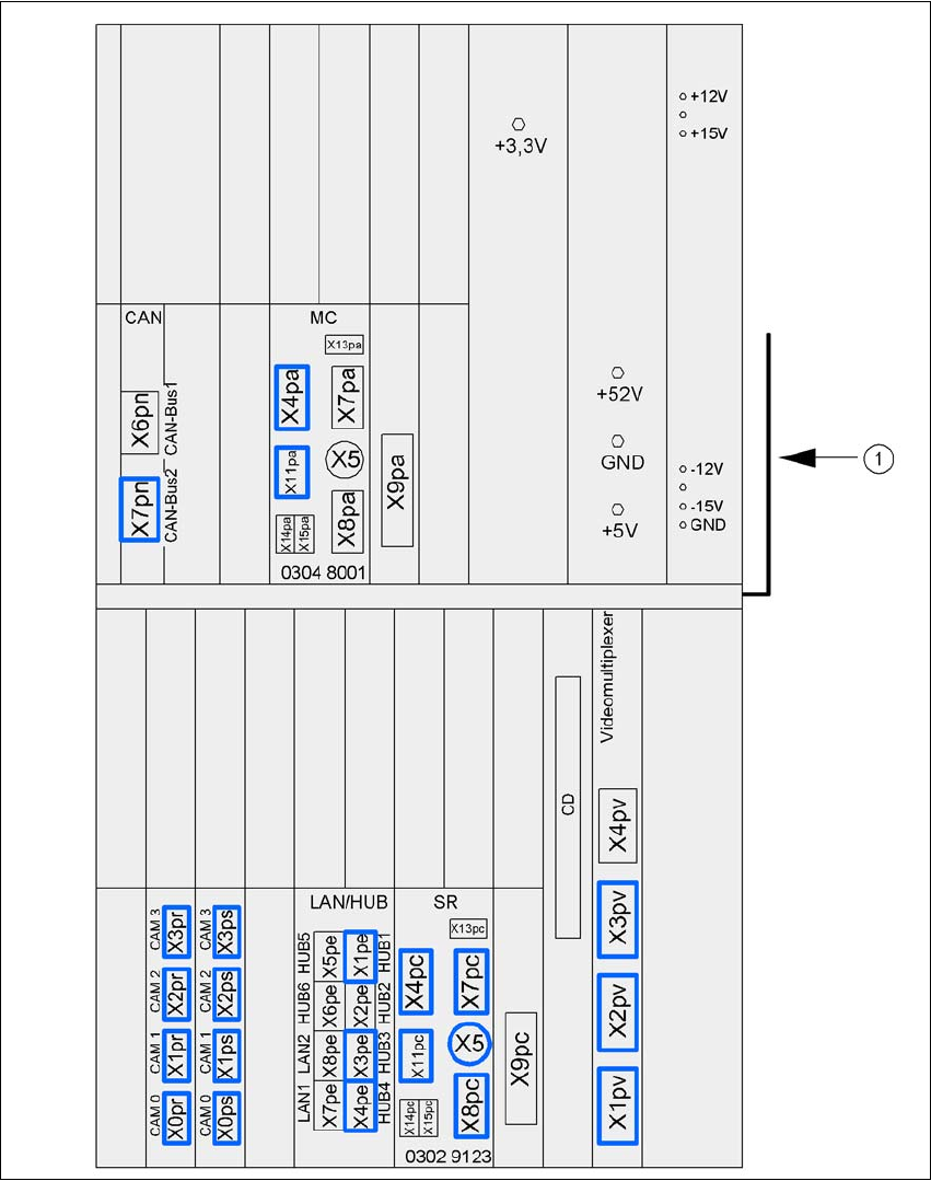
4.5.12 Installation of the Computer Unit of the CA4 and CA3
4.5.12.1 Computer Unit - Electrical Connection Points
4
Fig. 4.5 - 21 Computer unit, front panel - Connecting the plugs
(1) Cable guide plate