00195941-03-UM SiplaceCA-EN.pdf - 第396页
6 Component and Die Handling User Manual SIPLACE CA 6.1 X Feeder Modules for the Component Trolley from the SIPLACE X Series Edition 0 8/2011 EN 396 6.1.4.1 Description The energy and data inter face allows X feeder modu…
User Manual SIPLACE CA 6 Component and Die Handling
Edition 08/2011 EN 6.1 X Feeder Modules for the Component Trolley from the SIPLACE X Series
395
6.1.4 Energy- and Data Interface for the X-Feeder Modules
[00141247-xx] Energy and data interface for X feeders
6
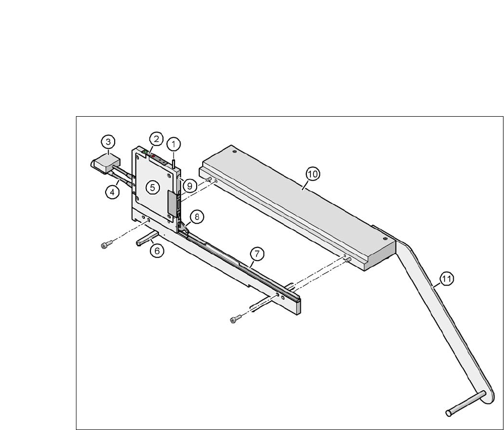
Fig. 6.1 - 16 Energy- and data interface for the X-feeder modules
(1) Release button for locking latch
(2) Operating panel
(3) Data cable
(4) Power supply cable
(5) Electronic housing
(6) Fold-out feet
(7) Omega profile for feeder guidance
(8) Locking latch
(9) Hole for front centering pin of feeder
(10)Base plate
(11) Reel holder

6 Component and Die Handling User Manual SIPLACE CA
6.1 X Feeder Modules for the Component Trolley from the SIPLACE X Series Edition 08/2011 EN
396
6.1.4.1 Description
The energy and data interface allows X feeder modules to be used outside the placement machine
and setup area. The interface consists of an aluminum frame with Omega profile (item 7 in fig. 6.1
- 15) for holding and guiding the feeder. As with the X component trolley, the feeder module is po-
sitioned on the Omega profile, with the guiding slides and is pushed forwards, until the front cen-
tering pin of the feeder has slid completely into the drilled hole provided (item 9 in fig. 6.1 - 15
).
The locking latch (item 8 in fig. 6.1 - 15
) locks the feeder in this position. To remove the feeder,
simply push the release button (item 1 in fig. 6.1 - 15
). The locking latch (item 8 in fig. 6.1 - 15) is
pressed down and the feeder is released. Fold-out feet (item 6 in fig. 6.1 - 15
) stabilize the position
of the energy and data interface, particularly in wider feeders.
The electronics housing (item 5 in fig. 6.1 - 15
) contains the control electronics fir the energy and
data interface. The operator panel (item 2 in fig. 6.1 - 15
) consists of the start and stop buttons,
plus two LEDS for the status display. Communication with a PC is established via a data cable
(item 3 in fig. 6.1 - 15
). The power supply cable (item 4 in fig. 6.1 - 15) is connected to the power
supply provided.
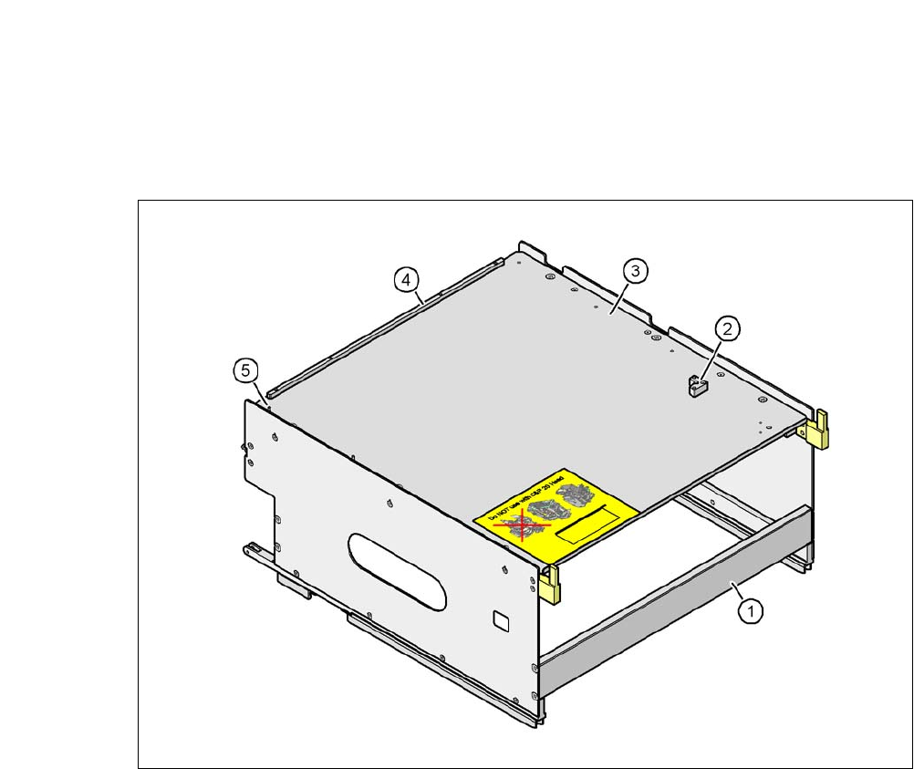
6.1.4.2 Application
The energy and data interface is used to check, maintain and repair X feeder modules. It can also
be used for setting up in advance for PCB production. In this case, the energy and data interface
is fixed to the base plate (item 10 in fig. 6.1 - 18
). The reel holder (item 11 in fig. 6.1 - 18) is also
mounted on the base plate. When a component tape is inserted, you can check or reset the incre-
ment, pickup position and conveyor speed. The detailed user manual describes how to use the
interface and the necessary servicing work.
6.1.4.3 Deliverables
– Single Slot EDIF
a
– Power supply, 100 - 120 / 200 - 240 VAC, +30VDC, 4.3 A
– Base plate with coil arm
– User manual
a) EDIF = energy and data interface
User Manual SIPLACE CA 6 Component and Die Handling
Edition 08/2011 EN 6.1 X Feeder Modules for the Component Trolley from the SIPLACE X Series
397
6.1.5 Waffle Pack Tray Holder for SIPLACE X Series Component Trolleys
[00141285-xx] Waffle pack tray holder for X series
6
Fig. 6.1 - 17 Waffle-pack tray holder
(1) Waffle-pack tray holder from the SIPLACE X-series
(2) Bracket for 2nd JEDEC magazines
(3) Waffle tray carrier
(4) Stop bars for JEDEC waffle pack tray
(5) Aligning pin - zero point of JEDEC waffle pack tray
6
Individually fitted JEDEC waffle-pack trays or waffle-pack magazines can be fixed to the waffle-
pack tray carrier using magnets. If two JEDEC waffle-pack trays are fitted, you must fix them with
locking and retaining rails, as used for the waffle-pack tray carrier on the MTC2.
Parts:
Magnet [00316593-xx]
Locking and holding rail for JEDEC magazines [00372615-xx]