00195941-03-UM SiplaceCA-EN.pdf - 第284页
4 Setting Up and Commissioning User Manual SIPLACE CA 4.5 Setting Up the Placement Machine Edition 08/2011 EN 284 4.5.7.5 Fitting the Ground Cable for the Doo r s Fasten the two ground cabl es for the doors (item 4 in …

User Manual SIPLACE CA 4 Setting Up and Commissioning
Edition 08/2011 EN 4.5 Setting Up the Placement Machine
283
4
CAUTION 4
Make sure that this half of the extension kit does not collide with the hexagonal shaft of the
PCB conveyor and thus bend the shaft.
Insert the mandrel (item 5 in fig. 4.5 - 9) for the conveyor cover into the drilling (item 6 in fig.
4.5 - 9
) on the second half of the extension kit.
Position the second half of the extension kit so that the assembly bracket lies on the assembly
bar (item 7 in fig. 4.5 - 8
).
Fasten this second half of the placement machine with 2 fillister head screws M6x16 and the
corresponding disc (item 3 in fig. 4.5 - 8
).
4.5.7.3 Fastening the Hexagonal Shaft Guidance
When using a single conveyor, fasten one guidance for the hexagonal shaft (item 8 in fig. 4.5
- 7) onto the extension kit, with two fillister head screws M6x16 and discs.
When using a dual conveyor, fasten two guidances for the hexagonal shaft (item 8 in fig. 4.5
- 7) onto the extension kit, with two fillister head screws M6x16 and discs.
4.5.7.4 Establishing Cable Connections - Extension Kit on the PCB Output Side
4
4
Left-hand side of the extension kit
(viewed in the direction of travel)
Connector/cable To connector/cable
EMERGENCY STOP button
Start/Stop button
X63/03020687 X63/03002526
Protective cover switch, location 3
X53/03020409 X53/03002528
Button for the component trolley docking unit,
location 3
X232/03021056 X232/03021053
Right-hand side of the extension kit
(viewed in the direction of travel)
Connector/cable To connector/cable
Start/Stop button
Switch, PCB conveyor cover
X62/03020410 X62/03002525
Protective cover switch, location 2
X52/03006476 X52/03002527
Button for the component trolley docking unit,
location 2
X222/03021056 X222/03021052
4 Setting Up and Commissioning User Manual SIPLACE CA
4.5 Setting Up the Placement Machine Edition 08/2011 EN
284
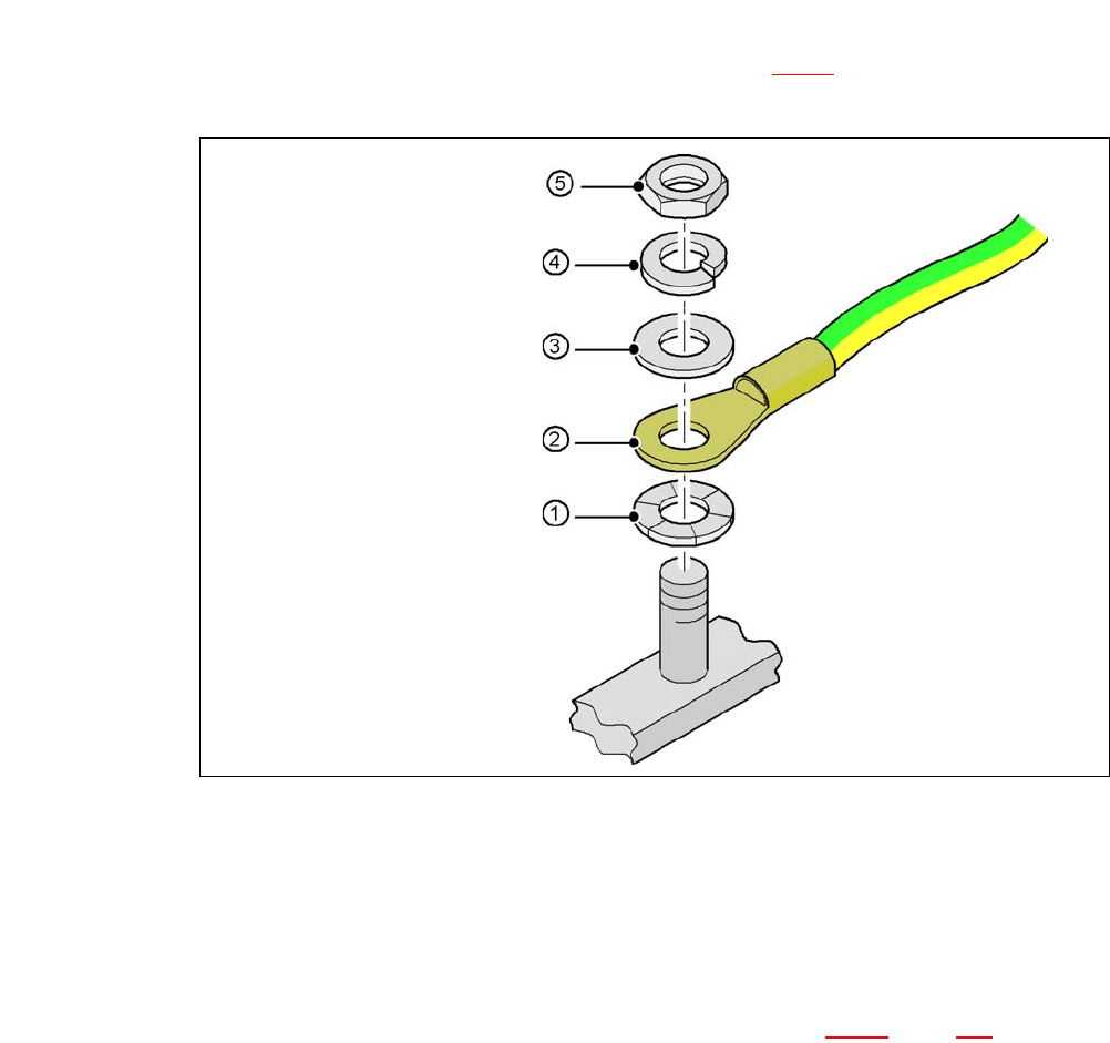
4.5.7.5 Fitting the Ground Cable for the Doors
Fasten the two ground cables for the doors (item 4 in fig. 4.5 - 8) to the machine frame as
follows:
4
Fig. 4.5 - 10 Fitting the grounding cable
4
4
4
4
4
4.5.7.6 Checking and Setting the Protective Cover Switch
Check the function of the protective cover switch (item 7 in fig. 4.5 - 9, page 282).
Adjust the protective cover switch if necessary (see Service Manual).
Hex nut M5
Spring washer M5, DIN 7980
Washer M5, DIN 125
Cable lug, annular
Contact washer
User Manual SIPLACE CA 4 Setting Up and Commissioning
Edition 08/2011 EN 4.5 Setting Up the Placement Machine
285
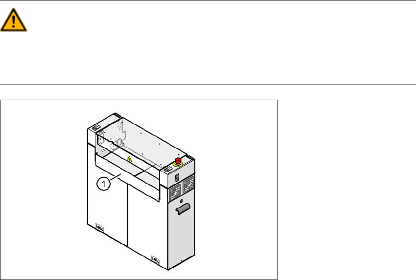
4.5.7.7 Installing the Bottom Hand Guard
The placement machines are only supplied with one bottom hand guard. However, if the place-
ment machines are installed in a line, there will be no hand guard between neighboring output and
input conveyors.
WARNING 4
Always fit the bottom hand guard at the input side of the first placement machine and on the out-
put side of the last placement machine in a line [03003432-01] with 4 hexagon socket-head
screws M4x12. This prevents unauthorized access to the inside of the machine.
4
Fig. 4.5 - 11 Fitting the "bottom" hand guard on the PCB output side
(1) Bottom hand guard [03003432-01]