00195941-03-UM SiplaceCA-EN.pdf - 第452页
7 Station Enlargements User Manual SIPLACE CA 7.1 Nozzle Changer Edition 08/2011 EN 452 7.1.4.5 Functional Description The nozzles are located in nozzle garages and ar e fixed by a mo vable locking pl ate. A pneumatic cy…
User Manual SIPLACE CA 7 Station Enlargements
Edition 08/2011 EN 7.1 Nozzle Changer
451
7.1.4.3 Technical Data
7
7.1.4.4 Assembly
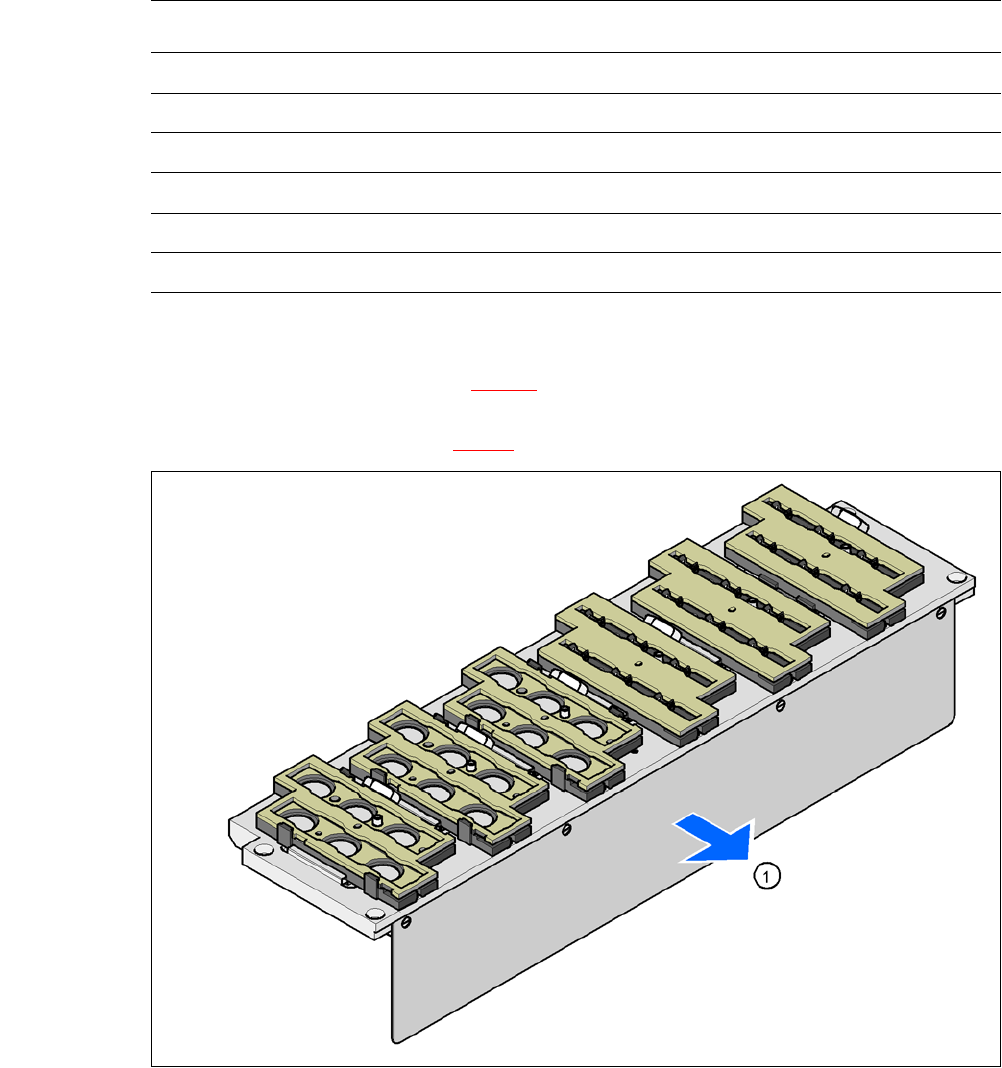
The nozzle changer "row 1" (see fig. 7.1 - 20) is fixed to the component trolley docking unit. There
is an additional assembly kit for the "row 2" nozzle changer. This consists of a take-off device and
reject bin for nozzles (see section 7.1.4.9
).
7
Fig. 7.1 - 22 Assembly position
(1) Cover plate pointing toward the PCB conveyor
Align the nozzle changer so that the cover plate (item 1) points toward the PCB conveyor.
Nozzle changer for the 6 segment Collect&Place CA head
Dimensions (length x width x height) 448 x 122.5 x 97.7 mm³
Number of magazines min. 1 / max. 6 with each 6 nozzle garages-
Number of nozzle holders 36
Nozzle types 8 xx, 9 xx
Nozzle changeover time approx. 2s per nozzle
Compressed air connection 0.48 MPa (4.8 bar)
7 Station Enlargements User Manual SIPLACE CA
7.1 Nozzle Changer Edition 08/2011 EN
452
7.1.4.5 Functional Description
The nozzles are located in nozzle garages and are fixed by a movable locking plate. A pneumatic
cylinder moves the locking plate by 12 mm. Depending on the position of the locking plate, all noz-
zles are either clamped into place or released. The default position of the locking plate, i.e. if there
is no nozzle change in progress, is "closed".
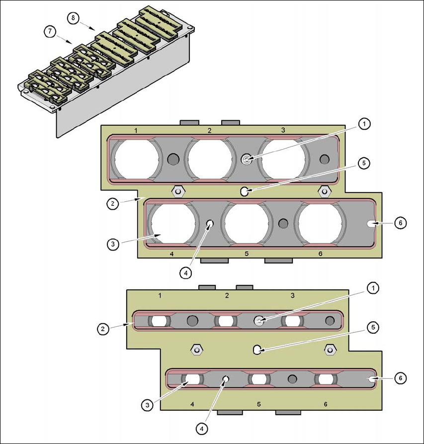
Every magazine of the nozzle changer has a positioning fiducial for position detection. The mag-
azine locations are numbered from 1-6 for the nozzle changers of "row 1" and from 7-12 for the
"row 2" nozzle changers (see fig. 7.1 - 20
). The 6 nozzle garages in the magazines are also num-
bered consecutively (see fig. 7.1 - 23
).
NOTE 7
Special magazines can be made after consulting with ASM Assembly Systems GmbH & Co.KGa
and receive a seperate marking.
Nozzle Pick Up 7
– The Z-axis of the Collect&Place CA head moves downwards.
– The locking plate (item 2 in fig. 7.1 - 23
, page 453) opens and releases the nozzles.
– The nozzle is taken up by the sleeve of the Collect&Place CA head.
– The Z axis moves up.
Placing a Nozzle Down 7
– The locking plate (item 2 in fig. 7.1 - 23, page 453) opens and releases the nozzles.
– The Z-axis of the Collect&Place CA head moves downwards and places the nozzle down.
– The locking plate closes.
– The Z-axis of the Collect&Place CA head moves upwards.
Rejecting Defective Nozzles 7
– At the reject unit (item 4 in fig. 7.1 - 20) the Z-axis of the Collect&Place CA head moves down-
wards by 14 mm and transfers the defective nozzle to the hole of the reject unit.
– The Z axis moves up again and the nozzle is stripped from the sleeve by spring wires.
– The nozzle drops into the reject bin.
User Manual SIPLACE CA 7 Station Enlargements
Edition 08/2011 EN 7.1 Nozzle Changer
453
7
Fig. 7.1 - 23 Magazine and nozzle holders
(1) Position fiducial
(2) Locking plate
(3) Nozzle garage for nozzles of type 9xx and 8xx
(4) Hole for cylinder pin to center the magazine
(5) Hole for cylinder pin of the push mechanism
(6) Longhole for cylinder pin to center the magazine
(7) Magazine for
type 8 xx nozzles
(8) Magazine for type 9 xx nozzles