00195941-03-UM SiplaceCA-EN.pdf - 第379页
User Manual SIPLACE CA 6 Component and Die Handling Edition 08/2011 EN 6.1 X Feeder Modules for the Component Trolley from the SIPLACE X Series 379 6 The maximum he ight of the interfe ring edges a bove the upper edge ot…
6 Component and Die Handling User Manual SIPLACE CA
6.1 X Feeder Modules for the Component Trolley from the SIPLACE X Series Edition 08/2011 EN
378
6.1.1.2 Tape Reel Diameter
The tape reel diameter may be up to 19" (483 mm) for all feeder modules. For a list of the maxi-
mum tape reel diameters, in accordance with the PCB conveyor heights, please refer to section
6.2.7.2
, page 411.
6.1.1.3 Manual Removal of Tantalum Capacitors that Were Not Picked Up by the Operator
To ensure that tantalum capacitors do not cause the tape material to burn when it is cut as a result
of pickup errors, the user interface has been extended to include the "Remove component from
tape in the event of a pickup error" option. You need to enable this option in SIPLACE Pro. On the
placement machine,
the component that was not picked up is paced forward again until it is ready for removal from the
component tape. The track is deactivated and the operator is sent an error message to remind
him to pick up the tantalum component from the tape.
If an alternative track is available, the machine continues placing. The operator is able to stop the
machine, however, and pick up the tantalum component.
If no alternative track is available and it is not possible to continue placement with other compo-
nents, the machine will stop. At this point, the operator can again remove the tantalum component
and acknowledge the error. Once the operator has restarted the machine, placement is continued
and components are picked up from the track that is now enabled once more.
NOTE 6
This software function is also a good idea for expensive components. Make sure you also observe
the safety instructions for capacitors on metallic powder basis ( see section 2.6.2 page 69).
6.1.1.4 Tape Feeder Geometry for SIPLACE X Series
NOTE 6
In the CA series, SIPLACE X series changeover tables are used in conjunction with X series tape
feeders. These are fully compatible with CA series placement machines and can be exchanged
and combined as required.
There are no special feeders for the CA series.
In general, the tape feeder modules from the X-series are approx. 587 mm long and approx. 200
mm high. The width and the number of locations that it fills on the component table are listed in
the following table.

User Manual SIPLACE CA 6 Component and Die Handling
Edition 08/2011 EN 6.1 X Feeder Modules for the Component Trolley from the SIPLACE X Series
379
6
The maximum height of the interfering edges above the upper edge ot the tape pocket is 3 mm.
Since the feeding modules do not posses any possibly standing up flaps and furthermore are
firmly anchored at the component table, the danger of a head crash is reduced to a minimum.
Tape feeder
modules
Feeder module width in
millimeters
Feeder module locations
required on the component
table
8 mm X 10,8 1
12 mm X 22,6 2
16 mm X 34,4 3
24 mm X 34,4 3
32 mm X 46,2 4
44 mm X 58,0 5
56 mm X 69,8 6
72 mm X 81,6 7
88 mm X 105,2 9
6 Component and Die Handling User Manual SIPLACE CA
6.1 X Feeder Modules for the Component Trolley from the SIPLACE X Series Edition 08/2011 EN
380
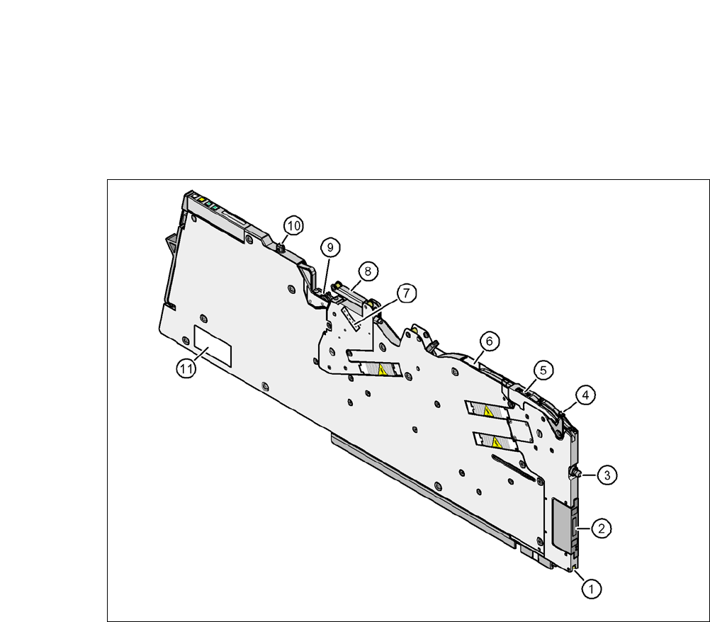
6.1.1.5 Design of SIPLACE X Series Tape Feeders
The two following diagrams show the design of the tape feeder module for the X-series with ref-
erence to the 8 mm X tape feeder module.
6
Fig. 6.1 - 1 8 mm X tape feeder module - front view
(1) Locking roller (the locking latch of the component table locks the feeder module in its end po-
sition with the locking roller.)
(2) EDIF (energy and data interface)
(3) Front centering pin
(4) Lever for raising the pickup window in order to thread in and remove the component tape
(5) Pickup window
(6) Outlet of the tape guide channel
(7) Setting the cover foil tension
(8) Cover foil rocker
(9) Cover foil packing wheels
(10)The back centering pin
(11) Type plate