00195941-03-UM SiplaceCA-EN.pdf - 第330页
4 Setting Up and Commissioning User Manual SIPLACE CA 4.7 Adapting the SIPLACE X-Series Component Trol ley to the PCB Conveyor Heig ht Edition 08/2011 EN 330 4 Fig. 4.7 - 2 fastening the assembly guide to the changeover …
User Manual SIPLACE CA 4 Setting Up and Commissioning
Edition 08/2011 EN 4.7 Adapting the SIPLACE X-Series Component Trolley to the PCB Conveyor Height
329
4.7.1 Warning Instructions
WARNING 4
Only technicians of the company ASM Assembly Systems GmbH & Co.KG or other certified per-
sonel may change the height of the component table.
Always follow the applicable accident prevention regulations.
Remove all the feeder modules from the component table, if you want to adjust the height for
the component feeder table.
4.7.2 Tools and Equipment
You will need the following tools and equipment to adjust the height of the component trolley:
– Hammer
–Punch, 8 mm
– Assembly guide [03015976-xx]
– Lifting device for raising the component trolley table, carrying capacity at least 80 kg
4.7.3 Changing the Component Trolley Height
WARNING 4
Remove all the feeder modules from the component table.
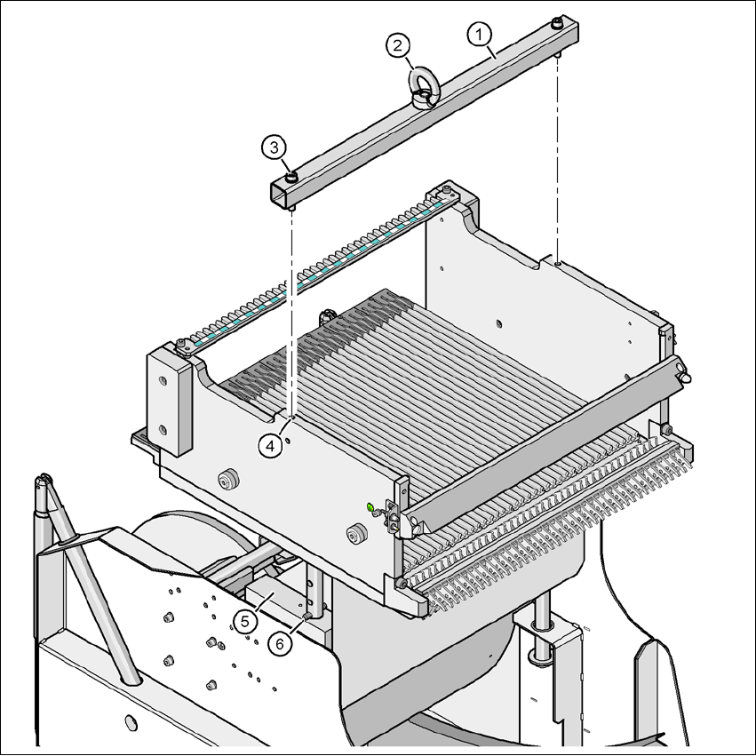
Fit the assembly guide to the component table in order to adjust the height. This prevents the
component table becoming deformed when the table is raised or lowered.
Fasten the assembly guide (item 1 in fig. 4.7 - 2) with the two hexagon socket-head screws
M8 x 50 (item 3 in fig. 4.7 - 2
) to the changeover table (item 4 in fig. 4.7 - 2).
Hook the lifting device into the eyelet (item 2 in fig. 4.7 - 2).
Lift the component trolley table slightly, until the split pins (item 6 in fig. 4.7 - 2) are accessible.
Use the punch to carefully tap out the split pins on both sides.
Insert the split pins into the drillings for the required PCB conveyor height (see fig. 4.7 - 1).
Slowly lower the component trolley table, until the split pins lie on the supporting blocks (item
5 in fig. 4.7 - 2
).
Dismantle the assembly guide
4 Setting Up and Commissioning User Manual SIPLACE CA
4.7 Adapting the SIPLACE X-Series Component Trolley to the PCB Conveyor Height Edition 08/2011 EN
330
4
Fig. 4.7 - 2 fastening the assembly guide to the changeover table of the SIPLACE component trolley
(1) Mounting aid
(2) Eyelet
(3) Hexagon socket head screw DIN 912, M8 x 50, 2 x
(4) M8 threaded hole in the component table, 2x
(5) Supporting block, 2x
(6) Split pin, DIN 7343, 8 x 40 - St, 2 x
User Manual SIPLACE CA 4 Setting Up and Commissioning
Edition 08/2011 EN 4.8 Adapting the Length of the SIPLACE X Used Tape Channel to the PCB Conveyor Height
331
4.8 Adapting the Length of the SIPLACE X Used Tape
Channel to the PCB Conveyor Height
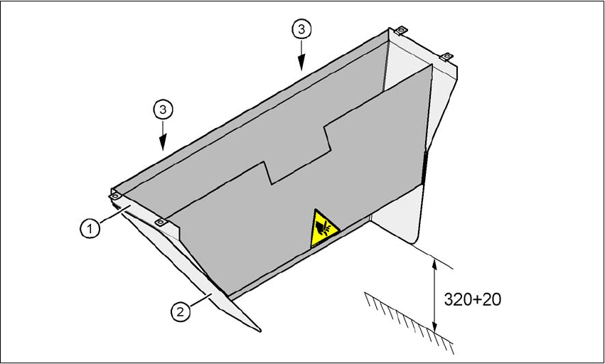
Depending on the PCB conveyor height, the length of the waste tape channel can be set so that
the pieces of tape are diverted directly into the waste tape bin of the component trolley.
4
Fig. 4.8 - 1 Adapting the length of the used tape channel (X-series) - Dimensions in millimeters
(1) Used tape channel
(2) Extension
(3) Hexagonal nut M4, DIN 985, 2 x
4.8.1 Tools
– Fork wrench, size 7