00195941-03-UM SiplaceCA-EN.pdf - 第416页
6 Component and Die Handling User Manual SIPLACE CA 6.5 Docking Station for SIPLACE X Series Component Trolley Edition 08/2011 EN 416 The basic tasks of the dockin g station are as follows: – Supplying the component tro …
User Manual SIPLACE CA 6 Component and Die Handling
Edition 08/2011 EN 6.5 Docking Station for SIPLACE X Series Component Trolley
415
6.5 Docking Station for SIPLACE X Series Component
Trolley
[00116933-xx] Docking station for SIPLACE X component trolley
6.5.1 Overview
The docking station is an additional component the setup area. It forms the link between the setup
area and the component trolley for the SIPLACE X-series. The docking station allows the compo-
nent trolleys to be set up with feeder modules and function tests and setup checks to be carried
out externally.
6
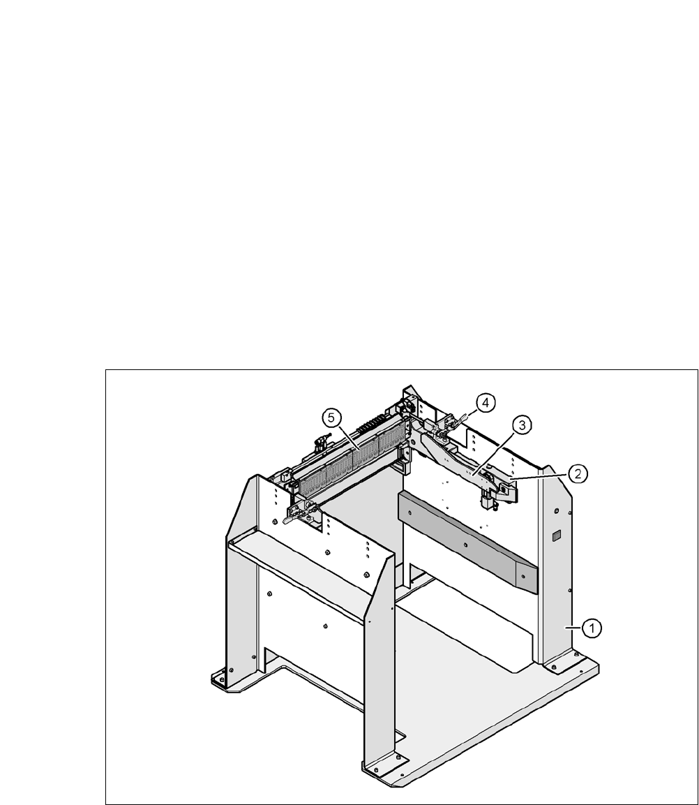
Fig. 6.5 - 1 Docking station, SIPLACE X-series
(1) Docking station
(2) X-series component trolley docking unit
(3) Rails for guiding and docking in the component table
(4) Horizontal tensioners for locking the component trolley
(5) EDIF (energy and data interface)

6 Component and Die Handling User Manual SIPLACE CA
6.5 Docking Station for SIPLACE X Series Component Trolley Edition 08/2011 EN
416
The basic tasks of the docking station are as follows:
– Supplying the component trolley and X feeder modules with power
– Supplying the component trolley and X feeder modules with compressed air
– Providing an infrastructure for communication between the PC at the setup area and the
feeder modules
6.5.2 Functional Description
The operator can use the docking station to carry out function tests on the X feeder modules and
check the setup outside the production environment. Two rows, each with four docking stations,
are connected via the CAN bus of the initial setup PC. Each docking station has a separate power
and compressed air connection.
The component trolley docking unit (item 2 in fig. 6.5 - 1
) of the docking station can be adjusted
to the required PCB conveyor height. The component trolley is moved into the docking station
(item 1 in fig. 6.5 - 1
) for the pre-setup configuration. The component trolley slides on the rails of
the component trolley docking unit, using the roller bearings attached to the sides of the compo-
nent trolley, to the energy and data interface connection. The changeover table and feeder EDIF
are aligned in the optimum position to the EDIF (item 4 in fig. 6.5 - 1
) of the component trolley
docking unit and are then fixed in this position with the two horizontal tensioners.
6.5.3 Technical Data
6
Dimensions
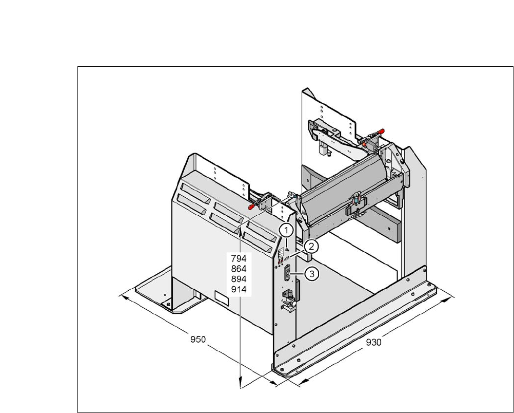
Length x width 950 mm x 930 mm
Height 794 mm for 830 mm PCB conveyor height
864 mm for 900 mm PCB conveyor height
894 mm for 930 mm PCB conveyor height
914 mm for 950 mm PCB conveyor height
Weight 120 kg
Compressed air supply ratings
p
min
p
max
0.5 MPa (5.0 bar)
1.0 MPa (10.0 bar)
Compressed air connection Coupler plug KS 2-M5-A
Compressed air consumption 50 Nl/min.
a
a) Under normal atmospheric conditions at 20°C and 1013 hPa
Connectionvoltage 88 - 264 VAC
Nominal current 3.5 A (230 VAC)
7 A (115 VAC)
Nominal apparent power 0.8 kW
Fuse protection 2 x 8 A
User Manual SIPLACE CA 6 Component and Die Handling
Edition 08/2011 EN 6.5 Docking Station for SIPLACE X Series Component Trolley
417
6
Fig. 6.5 - 2 Docking station - Dimensions in millimeters, connection points
(1) Compressed air connection
(2) CAN bus connection
(3) Power supply connection