00195941-03-UM SiplaceCA-EN.pdf - 第92页
2 Operational Safety User Manual SIPLACE CA 2.8 Safety Equipment Edition 08/2011 EN 92 2.8.4.1 Stru cture of the SIPLACE EMERGENCY ST OP Circuits The following contact s are series-connecte d and form the EMERGENCY STOP …

User Manual SIPLACE CA 2 Operational Safety
Edition 08/2011 EN 2.8 Safety Equipment
91
Protective contactor combination 3TK2806 2
The protective contactor combination is contained in the power supply unit. It is used to monitor
the EMERGENCY STOP circuits and safety equipment.
There are three conditions that must be fulfilled in order to activate the protective contactor com-
bination:
– The "software enable" signal must have been sent.
– The EMERGENCY STOP circuit must be closed.
– The Start button must have been pressed.
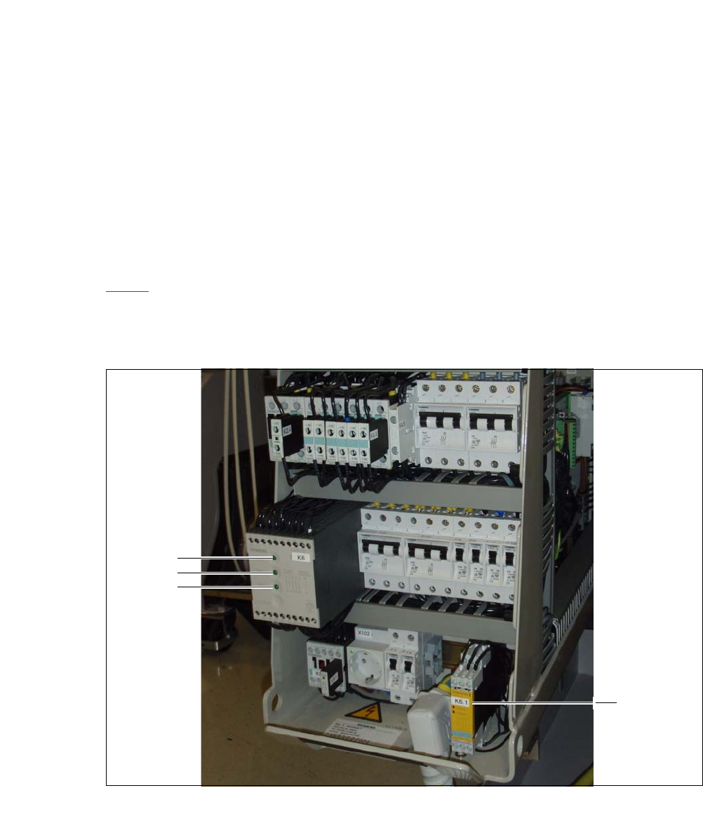
The front side of the protective contactor combination has three green LEDs for the status display
(see fig. 2.8 - 7
, page 92):
– The "Mains" LED indicates that voltage is present.
– The "Channel 1" and "Channel 2" LEDs light up if the Start button was pressed, the EMER-
GENCY STOP circuit is closed and the signaling circuit is not signaling a fault status.
Service socket (item 2 in fig. 2.8 - 6) 2
The service socket is contained in the power supply unit and is protected by the cover. It can only
be used if the placement system is connected to the main power supply via a 5-wire connection
(L1, L2, L3, N, and PE). If a 4-wire connection is used, e.g. without N, the socket cannot be used.
WARNING 2
Always follow the safety instructions concerning potentially lethal voltages - even when the
placement system is switched off. (See section 2.1.5 from page 35)
2.8.4 EMERGENCY STOP Circuits and Signaling Circuit on SIPLACE and SWS
The EMERGENCY STOP functionality of the SIPLACE has been enhanced by the EMERGENCY
OFF circuit of the SWS. For this reason the switching device 3TK2830-1CB30 (K6.1) has been
integrated into the power supply unit of the SIPLACE (see the plan "Extension of SIPLACE CA
EMERGENCY STOP" [00386139]).
2 Operational Safety User Manual SIPLACE CA
2.8 Safety Equipment Edition 08/2011 EN
92
2.8.4.1 Structure of the SIPLACE EMERGENCY STOP Circuits
The following contacts are series-connected and form the EMERGENCY STOP circuit:
– normally open (NO) contacts for the four protective cover switches
– normally open (NO) contacts in the two protective switches for the cover flaps over the PCB
conveyor
– normally open (NO) contacts for the two EMERGENCY STOP buttons
– normally open (NO) contacts for the feeder module cover flaps (option)
– normally open (NO) contacts for the four component trolleys or SWSs (wafer feeders)
– channels of the protective contactor combination PCC 6 and the K6.1 (3TK2830-1CB30) ex-
tension
In the EMERGENCY STOP circuit 2, the CAN bus signal for the signaling circuit (see section
2.8.4.2
) is fed to channel 2 of the protective contactor combination PCC K6. If the EMERGENCY
STOP circuit is closed, and the signaling circuit is not signaling a malfunction, then the two green
LEDs for channels 1 and 2 light up, in addition to the green mains power check LED of the pro-
tective contactor combination.
2
Fig. 2.8 - 7 Signal LED on the protective contactor combination K6 and SWS EMERGENCY STOP switching device
K6.1
(1) Netz / Power
(2) Kanal 1 / Channel 1
1
2
3
4

User Manual SIPLACE CA 2 Operational Safety
Edition 08/2011 EN 2.8 Safety Equipment
93
(3) Kanal 2 / Channel 2
(4) SWS EMERGENCY STOP switching device
extension K6.1 (3TK2830-1CB30)
2.8.4.2 Structure of the Signaling Circuit
The signaling contacts of the protective switches for protective covers, for cover flaps above the
PCB conveyor, for component trolleys or the SWSs as well as for EMERGENCY STOP buttons
are polled individually. All the signaling contacts are closed when the machine is on standby. If a
protective cover, for example, is raised, the associated signaling contact opens. This change of
state is signaled to the control computer via the CAN bus. The relevant error message will be dis-
played on the user interface of the station computer and the SWS.
2.8.4.3 Functional Description of the SIPLACE EMERGENCY STOP Circuits
The following conditions must be fulfilled in order to start and operate the placement machine:
– The existing component trolley must be docked and connected.
– The SWSs must be inserted and connected (
EMERGENCY STOP interface connector X1x).
– The SWS EMERGENCY STOP circuits (1 per SWS) must be closed.
– All protective covers must be closed.
– Both cover flaps over the PCB conveyor must be closed.
– The EMERGENCY STOP buttons on the placement machine (2) and on the SWS (1) must
be released.
– The cover flaps (option) over the feeder modules must be closed.
– The minimum operating pressure must have been reached.
– The "software enable" signal must be active. This ensures that the safety circuit is closed.
– The power supply must be sending 24 V to the Start buttons and the protective contactor
combination.
– If one of the start buttons is pressed, the protective contactor combination PCC 6 and the ex-
tension K6.1 are actuated and activate the following components:
– 250 VDC link voltage for the servo amplifiers for the gantry axes
– 145 VDC link voltage for the star axes
– The axis unit receives a "Servo enable" signal for the servo amplifiers.
– 34 VDC operating voltage is switched to the component trolleys.
– 24 V operating voltage are being sent to the used tape cutters.
– The PCB conveyor control receives the enable signal for the PCB clamping, the PCB
stopper and the lifting table control.
Thus the machine is ready to operate.