00195941-03-UM SiplaceCA-EN.pdf - 第460页
7 Station Enlargements User Manual SIPLACE CA 7.1 Nozzle Changer Edition 08/2011 EN 460 7 Align the nozzle chan ger so that the m arking hole (item 1 ) is on the left, as viewed by the o p- erator . 7.1.5.3 Functional …
User Manual SIPLACE CA 7 Station Enlargements
Edition 08/2011 EN 7.1 Nozzle Changer
459
7.1.5.1 Technical Data
7
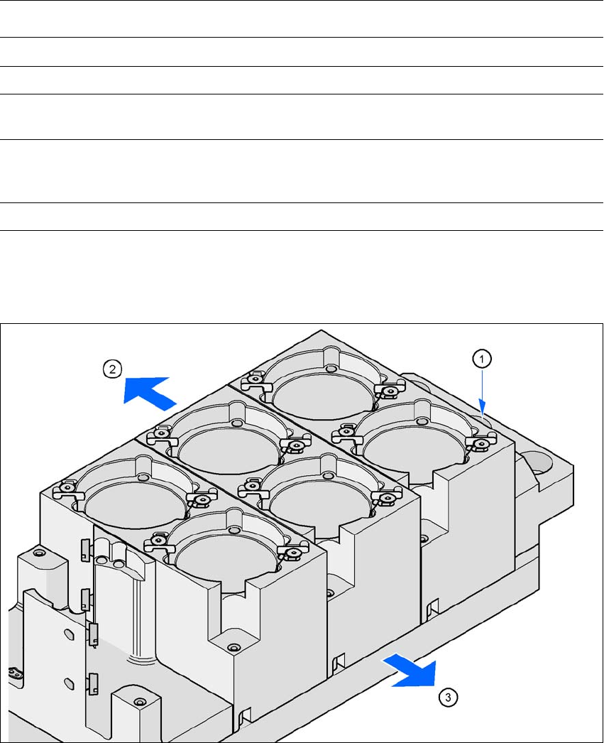
7.1.5.2 Assembly
The nozzle changer is fixed to the component trolley docking unit.
7
Fig. 7.1 - 28 Assembly position
(1) Marking hole
(2) Operator side
(3) Arrow pointing toward the PCB conveyor
Nozzle Changer for the SIPLACE TwinHead
Dimensions (length x width x height) 448 x 68 x 49 mm³
Number of magazines max. 12
Number of nozzle holders max. 24 standard nozzles
max. 12 special nozzles
Nozzle types 5xx, standard
4 xx with adapter
9 xx with adapter
Nozzle changeover time Approx. 2 s per nozzle
7 Station Enlargements User Manual SIPLACE CA
7.1 Nozzle Changer Edition 08/2011 EN
460
7
Align the nozzle changer so that the marking hole (item 1) is on the left, as viewed by the op-
erator.
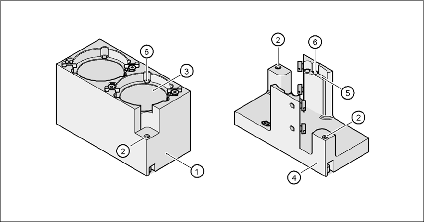
7.1.5.3 Functional Description
The magazine for standard nozzles has 1 positioning fiducial for position detection, while the mag-
azine for special nozzles/grippers has two. The nozzles are fixed in the garage with balls. The noz-
zles are either clamped or released for removal, depending on the rotary position of the DP axis.
7
Fig. 7.1 - 29 Magazine for standard and special nozzles
(1) Standard magazine
(2) Position fiducial
(3) Nozzle garage
(4) Magazine for special nozzles and gripper
(5) Nozzle garage
(6) Nozzle fixing balls
User Manual SIPLACE CA 7 Station Enlargements
Edition 08/2011 EN 7.2 Component Reject Bin Sensor
461
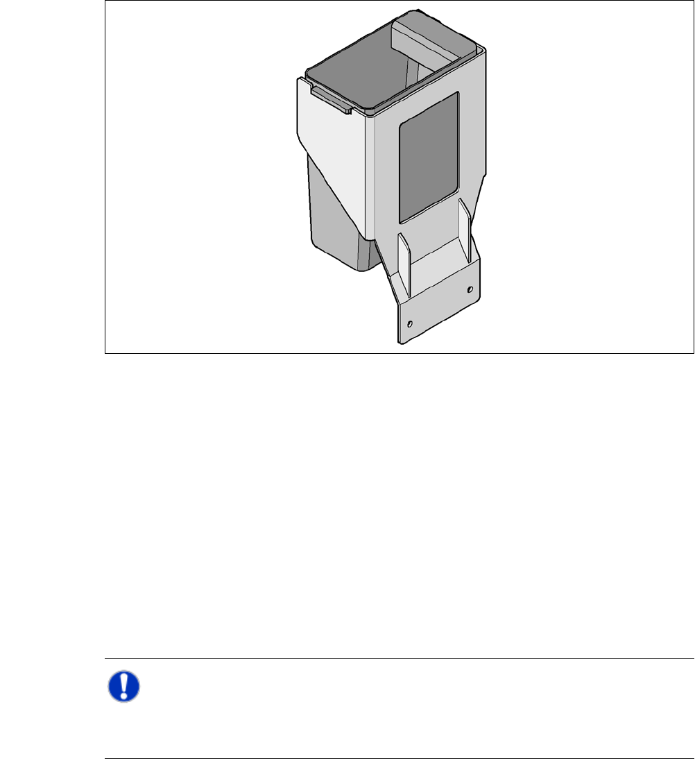
7.1.6 Component Reject Bin for the SIPLACE TwinHead
A component reject bin may be installed for the SIPLACE TwinHead. It is positioned next to the
fine pitch Vision module.
7
Fig. 7.1 - 30 Component reject bin for the SIPLACE TwinHead
7.2 Component Reject Bin Sensor
[00116848-xx]Query component reject bin X series/D3
The sensor for the component reject bin monitors whether the reject bin is seated correctly in its
mount.
– If the reject bin was not inserted correctly, the placement machine cannot be started.
– If the reject bin jumps out of its mount during the placement process, the machine is stopped
immediately to avoid a head crash.
Each reject bin can be monitored by a separate sensor.
NOTE 7
We recommend to install the optional component sensor for the component reject bin at a loca-
tion without SWS when a 20 segment Collect&Place head is used.