00195941-03-UM SiplaceCA-EN.pdf - 第332页
4 Setting Up and Commissioning User Manual SIPLACE CA 4.8 Adapting the Length of the SIPLACE X Used Tape Channel to the PCB Conveyo r Height Edition 08/2011 EN 332 4.8.2 Setting the Length of the Used T ape Channel 4.8.2…
User Manual SIPLACE CA 4 Setting Up and Commissioning
Edition 08/2011 EN 4.8 Adapting the Length of the SIPLACE X Used Tape Channel to the PCB Conveyor Height
331
4.8 Adapting the Length of the SIPLACE X Used Tape
Channel to the PCB Conveyor Height
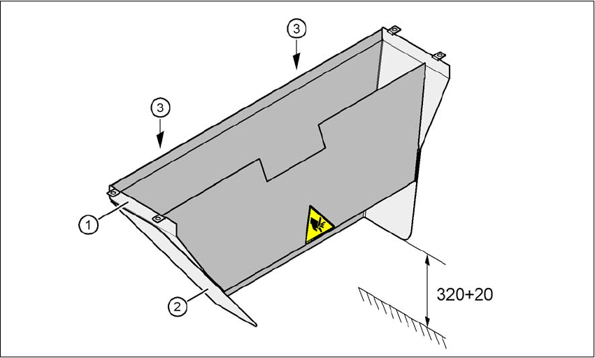
Depending on the PCB conveyor height, the length of the waste tape channel can be set so that
the pieces of tape are diverted directly into the waste tape bin of the component trolley.
4
Fig. 4.8 - 1 Adapting the length of the used tape channel (X-series) - Dimensions in millimeters
(1) Used tape channel
(2) Extension
(3) Hexagonal nut M4, DIN 985, 2 x
4.8.1 Tools
– Fork wrench, size 7

4 Setting Up and Commissioning User Manual SIPLACE CA
4.8 Adapting the Length of the SIPLACE X Used Tape Channel to the PCB Conveyor Height Edition 08/2011 EN
332
4.8.2 Setting the Length of the Used Tape Channel
4.8.2.1 830 mm PCB Conveyor Height
Loosen the two hexagonal nuts M4 (item 3 in fig. 4.8 - 1).
Remove the extension (item 2 in fig. 4.8 - 1).
4.8.2.2 900 mm - 950 mm PCB Conveyor Heights
Loosen the two hexagonal nuts M4 (item 3 in fig. 4.8 - 1).
Adjust the extension (item 2 in fig. 4.8 - 1) so that the distance between the bottom edge and
the base does not exceed a maximum of 320 mm + 20 mm (see fig. 4.8 - 1
).

User Manual SIPLACE CA 5 Tasks on the Machine
Edition 08/2011 EN 5.1 Profile
333
5 Tasks on the Machine
This chapter contains a number of subjects that are intended to help you during your daily work
on a SIPLACE line.
For example, you are provided with preventative measures that you can take to minimize the down
time on the machine to obtain the highest possible level of efficiency for the SIPLACE line during
production.
In addition, the tasks of the operator and of the line engineer are described in an operator and line
engineer profile, respectively, in this chapter.
5.1 Profile
5.1.1 Operator
5.1.1.1 Tasks of the Operator
The operators should generally have attended the SIPLACE operation training course or have
been instructed by trained personnel.
The operating personnel are to be assigned the following tasks:
– Checking the assignment of components to the feeder modules
To do this, a setup check is to be carried out several times a day, preferably at the start
of a shift, to make sure that the correct components are set up.
– Supplying the feeder modules with sufficient components
– Prompt refill of components, prompt splicing on of new tapes and change of the wafer mag-
azine
– Emptying the cover foil container (after every splicing operation, for example)
– Checking the components for correct pickup positions (see fig. 5.9 - 1
)
– Checking the flow of material to the PCBs on the input and output conveyor
– Checking the setup quality
– Random sampling of the PCBs before they enter the soldering furnace.
– Observing the ESD regulations
– Observing the fault displays and messages at the station and passing the information on to
the line engineer if necessary
– Carrying out the preventive maintenance work specified in the Preventive Maintenance Man-
ual