00195941-03-UM SiplaceCA-EN.pdf - 第99页
User Manual SIPLACE CA 2 Operational Safety Edition 08/2011 EN 2.9 Residual Voltages and Discharge Times 99 Fig. 2.9 - 2 Measuring point s on the power supply unit 2 2.9.1.1 Operating V olt ages, Residual V olt ages and …
2 Operational Safety User Manual SIPLACE CA
2.9 Residual Voltages and Discharge Times Edition 08/2011 EN
98
2.9 Residual Voltages and Discharge Times
2.9.1 (Placement) Machine
If the EMERGENCY STOP button is pressed or the placement system is switched off, the 250
VDC link voltage for the gantry axes and the 145 VDC link voltage for the star axes are reduced
to harmless residual voltages in a very short time.
WARNING 2
The placement system is supplied with 3 x 208 V~, 3 x 230 V~, 3 x 380 V~, 3 x 400 V~ or
3 x 415 V~ ± 5 %, 50/60 Hz mains voltage. This means that some parts of the system carry
potentially lethal voltages - even when switched off at the main power switch. Incorrect handling
of the placement system can therefore result in death or severe injury or considerable damage to
equipment.
Always follow the applicable accident prevention and DIN regulations (particularly DIN EN 60
204, part 1).
The guards over the power supply unit and the axis unit must ONLY be opened by appropri-
ately qualified and trained personnel.
2
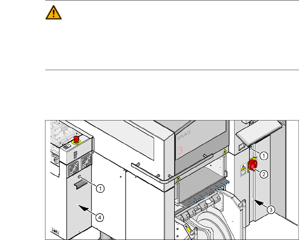
Fig. 2.9 - 1 Power supply unit
(1) Lock with bar in the cover
(2) Main switch
(3) Power supply unit behind the cover
(4) Axis unit
User Manual SIPLACE CA 2 Operational Safety
Edition 08/2011 EN 2.9 Residual Voltages and Discharge Times
99
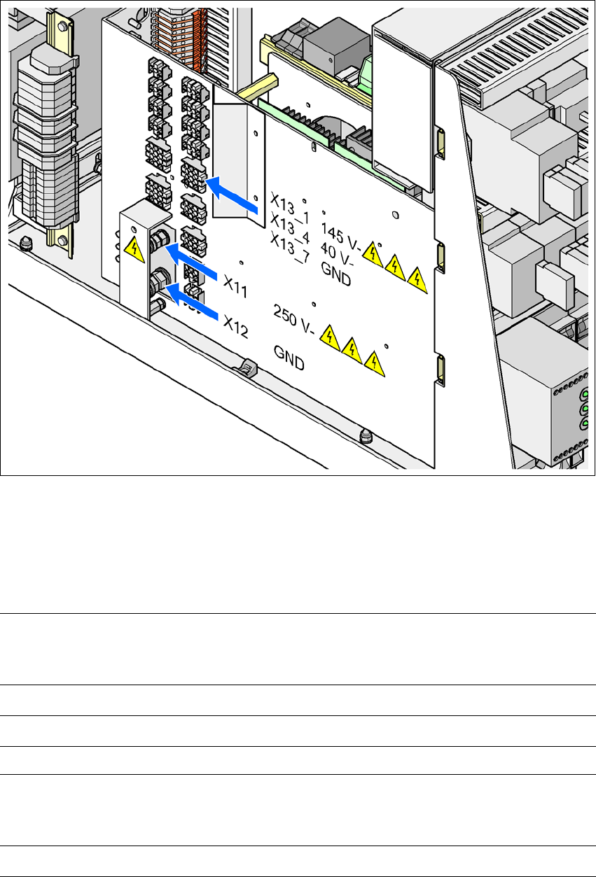
Fig. 2.9 - 2 Measuring points on the power supply unit
2
2.9.1.1 Operating Voltages, Residual Voltages and Discharge Times after Pressing
the EMERGENCY STOP Button
2
2
Pins X11 and X13_1
measured to X12 (GND)
Voltage in
normal mode
Residual voltage
after EMERGENCY
STOP
Discharge
times
X11 + 250 VDC < 10 VDC 7 s
X13_1 + 145 VDC < 10 VDC 50 s
Pin X13_4
measured to pin X3_7 (-)
Voltage in
normal mode
Residual voltage
after EMERGENCY
STOP
Discharge
times
X13_4 + 40 VDC + 40 VDC -
2 Operational Safety User Manual SIPLACE CA
2.9 Residual Voltages and Discharge Times Edition 08/2011 EN
100
2.9.1.2 Residual Voltages and Discharge Times after Switching off at the Main Switch
2
CAUTION 2
To avoid losing data, assess the following criteria before switching off your automatic placement
system (apart from in emergencies):
– Has the placement system finished transmitting machine, setup and panel data?
– Has the placement system finished processing the PCB?
– Has the placement system completed the run-up phase?
Pins X11, X13_1 and X13_4
measured to X12 (GND)
Residual voltages when
main power switch is off Discharge times
X11 < 10 VDC < 7 s
X13_1 < 10 VDC < 50 s
X13_4 < 10 VDC < 2 s