00195941-03-UM SiplaceCA-EN.pdf - 第157页
User Manual SIPLACE CA 3 Technical Data Edition 08/2011 EN 3.7 SIPLACE Wafer System (SWS) 157 3.7.4.4 Flip Chip Coded Positions (af ter Calibration) 3 3 Fig. 3.7 - 9 Flip Chip Coded Positions (after calibration) 0° Home …
3 Technical Data User Manual SIPLACE CA
3.7 SIPLACE Wafer System (SWS) Edition 08/2011 EN
156
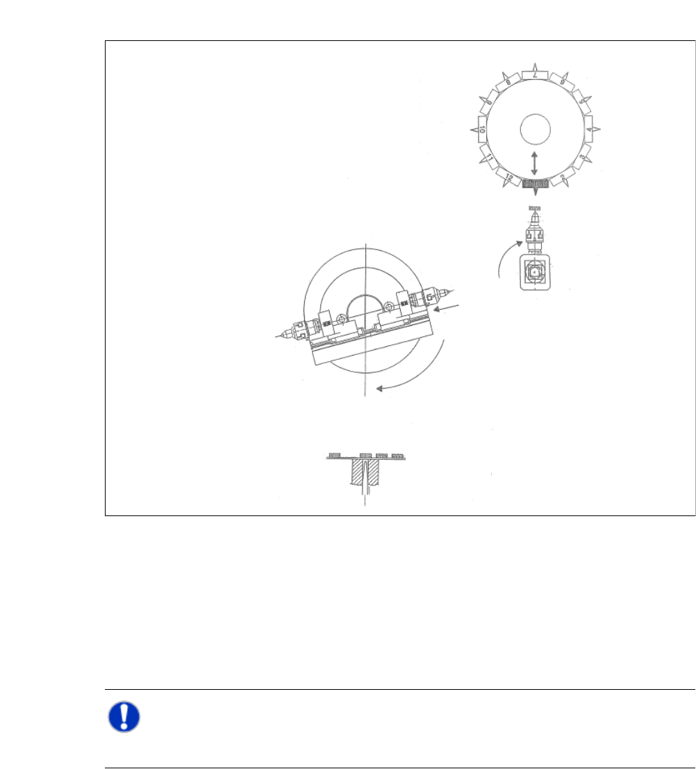
3.7.4.3 Die Attach Transfer Position
3
Fig. 3.7 - 8 Die Attach Transfer Position
(1) The die attach rotates to the transfer position.
(2) The SIPLACE head picks the chip up from the die attach segment and rotates to the next star
position.
(3) At the same time the X axis retracts the segment nr. 1 back into the home position.
(4) The flip chip unit - segment nr. 1 rotates to the transfer position and picks up the next chip.
NOTE 3
While using the die attach unit only the segment nr.1 of the flip chip unit is ative.
User Manual SIPLACE CA 3 Technical Data
Edition 08/2011 EN 3.7 SIPLACE Wafer System (SWS)
157
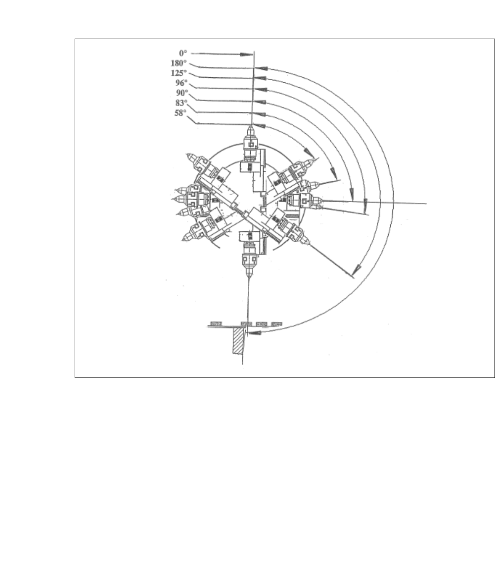
3.7.4.4 Flip Chip Coded Positions (after Calibration)
3
3
Fig. 3.7 - 9 Flip Chip Coded Positions (after calibration)
0°
Home sensor position
180°
Transfer position, segment 1
125°
Camera "free" position
96°
Discharge position, segment 1
90°
Home offset position
83°
Discharge position, segment 2
58°
Camera "free" position
3 Technical Data User Manual SIPLACE CA
3.7 SIPLACE Wafer System (SWS) Edition 08/2011 EN
158
3
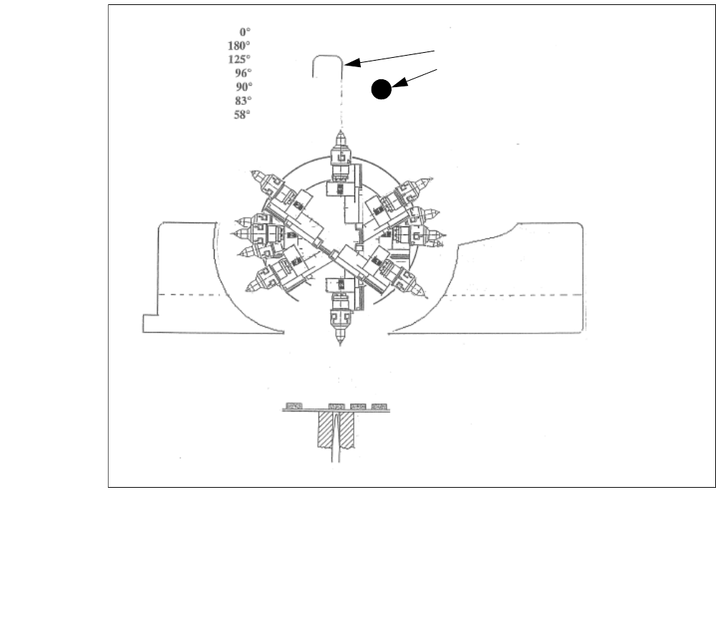
Fig. 3.7 - 10 Initialization of the flip roations axis
(1) Mechanical Stop
(2) Home sensor
The home sensor is used to initialize the flip rotation axis. During the initialization the rotation axis
travels slowly to discharge of the home sensor. Afterwards the first zero puls is looked up in an
aerea of 0-30° of the rotation axis. Through that the zero position of the flip rotation axis is defined.
Reject bin
Segment no. 2
Reject bin
Segment no. 1
1. Mechanical Stop
2. Home sensor