00195941-03-UM SiplaceCA-EN.pdf - 第257页
User Manual SIPLACE CA 4 Setting Up and Commissioning Edition 08/2011 EN 4.3 Delivery Configuration and Transpo rtation of SWS 257 4.3.3.3 Fork Lif t Attachment Point s on the SWS WA R N I N G 4 Lift the SWS at its metal…

4 Setting Up and Commissioning User Manual SIPLACE CA
4.3 Delivery Configuration and Transportation of SWS Edition 08/2011 EN
256
4.3.3 Transporting the SWS without Transportation Crate or Pallet
4.3.3.1 Safety Instructions
WARNING 4
The applicable accident prevention regulations concerning the transportation of heavy goods
must be followed.
In particular, you should wear safety boots to minimize the risk of crushing your feet.
– Before transporting the machine, read this section through carefully, to avoid damaging the
SWS.
4.3.3.2 Transportation Equipment
To transport the SWS, use a fork-lift truck or an appropriate hand-lift with the following specifica-
tions:
4
NOTE 4
The necessary width of the fork lift presents a critical measure. You should absolutely make sure
that the hand-lift used meets the required specifications.
Fork length Min. 1600 mm
Lifting power Min. 1500 kg
Outer fork width Min. 450 mm
Max. 520 mm
User Manual SIPLACE CA 4 Setting Up and Commissioning
Edition 08/2011 EN 4.3 Delivery Configuration and Transportation of SWS
257
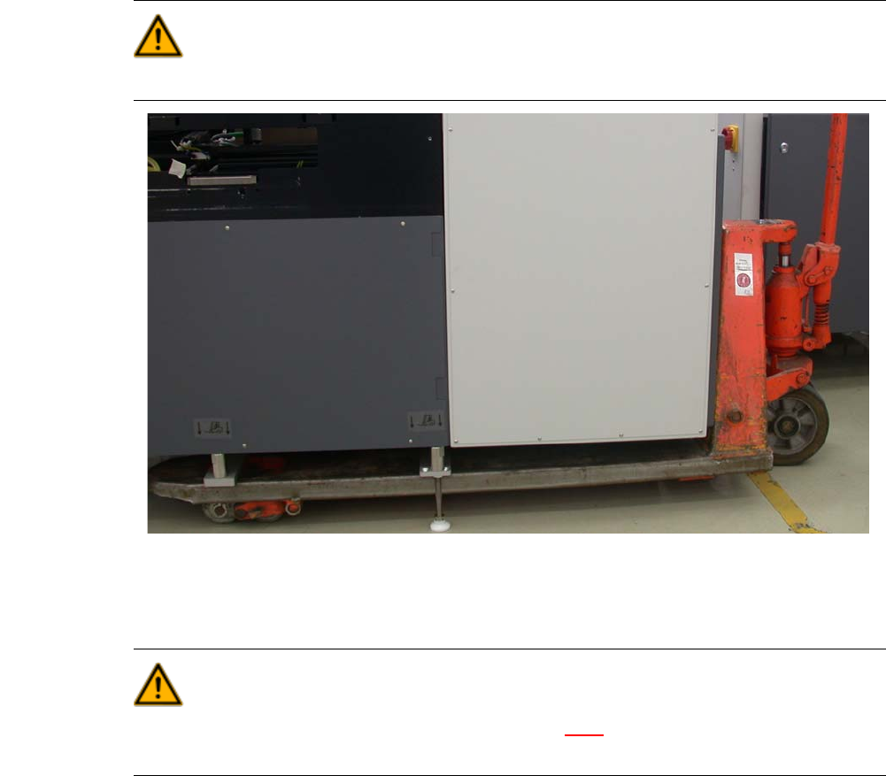
4.3.3.3 Fork Lift Attachment Points on the SWS
WARNING 4
Lift the SWS at its metal frame only.
Fig. 4.3 - 2 Attachment points at the SWS for fork-lift truck or hand-lift
4.3.3.4 Points that MUST be Noted when Transporting the SWS
WARNING 4
Consider the center of gravity of the SWS (see section 3.4.9
), especially when transporting it in
cross direction on the fork-lift or hand-lift.

4 Setting Up and Commissioning User Manual SIPLACE CA
4.4 Infrastructure of Installation Location Edition 08/2011 EN
258
4.4 Infrastructure of Installation Location
4.4.1 Recommendation for Foundation Quality
The foundation on which the placement machine or SWS is installed should be firm and level, as
dynamic forces can cause vibrations when the placement machine is operated. The size of the
vibrations depends on the construction of the foundation. The following are suitable provided that
the floor loading parameters, etc., are not exceeded:
– Reinforced concrete ceiling constructions, e.g. ceilings in production halls
– Reinforced concrete floor slabs, e.g. concrete floors in production halls without a basement
– Rooms with double floors, provided that a stable foundation is included in the space between
them. The same setup conditions apply to this intermediate foundation, which can be made
from steel girders or concrete.
4.4.1.1 Machine Weight and Floor Loading
The machine weights and floor loading values can be found in section 3.4.5, page 137.
4