00195941-03-UM SiplaceCA-EN.pdf - 第342页
5 Tasks on the Mach ine User Manual SIPLACE CA 5.2 Tasks on the SWS Edition 08/2011 EN 342 5.2.6 Checking and Fitting T ools and Nozzles to the Flip Unit Switch off the placement mach ine and the SWS properly . Open …
User Manual SIPLACE CA 5 Tasks on the Machine
Edition 08/2011 EN 5.2 Tasks on the SWS
341
5
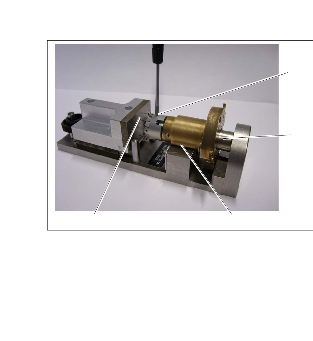
Fig. 5.2 - 4 Calibration standard for die-ejector
Insert the needle unit into the calibration standard for the die-ejector (1). During that the cen-
tering bolt (5) is inserted into the opening on the underside of the ejection unit.
Draw back the ejection unit until it lies fully in the prism. After releasing the crank at the ejec-
tion unit should now be pressed into a defined position against the limiter plate.
Move the alignment plate (2) towards the not clamped needles.
Move the alignment plate as far as the stop against the bolts, so the needles are adjusted by
the plate in one defined height.
Carefully screw in the grub screws (3) (approx. 10Ncm).
Make sure that no needles slipped. In case loosen the screws again and repeat the process.
1
5
2
3
5 Tasks on the Machine User Manual SIPLACE CA
5.2 Tasks on the SWS Edition 08/2011 EN
342
5.2.6 Checking and Fitting Tools and Nozzles to the Flip Unit
Switch off the placement machine and the SWS properly.
Open the protective cover above the SWS.
5
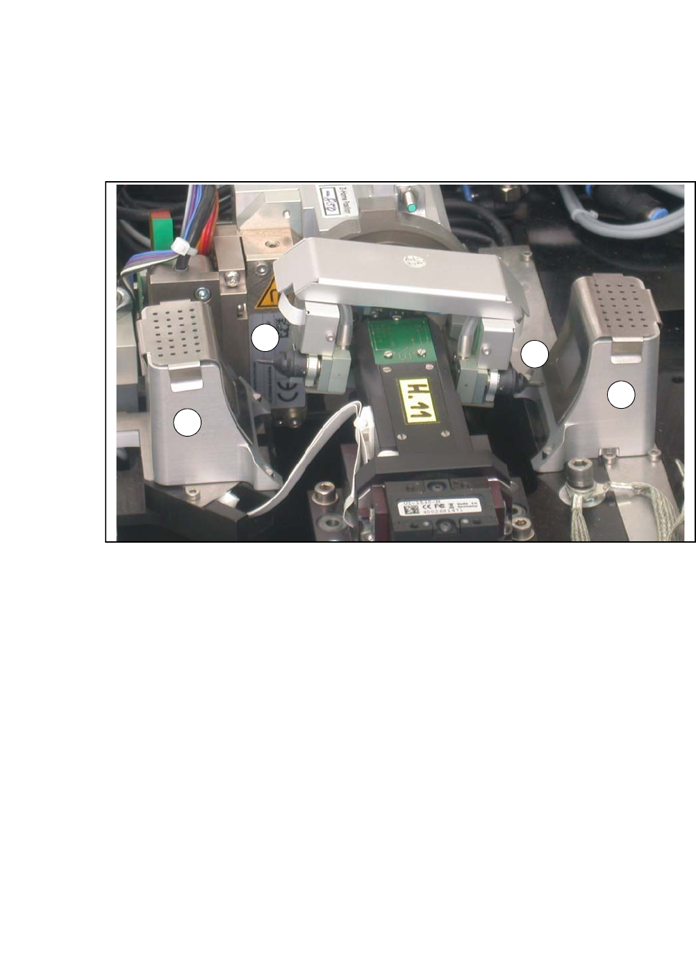
Fig. 5.2 - 5 Flip unit with nozzles and reject bins
Legend
5
Check the state and type of the nozzles and tools on the flip unit. If necessary, replace them
with new ones or those appropriate for the product.
You can either use the standard nozzles of the SIPLACE placement machines or rubber tips
together with an appropriate adapter.
Proceed with checking the reject bins.
5.2.7 Checking the Reject Bins of the Flip Unit
Check and empty the reject bins of the flip unit (item 2 in fig. 5.2 - 5).
When replacing the reject bins make sure that the underlying surface is clean and that the bin
is seated correctly in its fixation. Otherwise they are not recognized by the sensors.
Close the protective cover above the SWS.
Switch the SWS and the placement machine on.
(1) Nozzle segment 1 (2) Nozzle segment 2
(3) Reject bin
2
3
3
1

User Manual SIPLACE CA 5 Tasks on the Machine
Edition 08/2011 EN 5.3 Changing Shifts
343
5.3 Changing Shifts
Splice the tapes early. The feeder modules do not have to be refilled as soon as the new shift
starts. This minimizes extended down times.
At the shift change, pass important information on to the next operator. This includes, for in-
stance, changes to the placement program. Perform the steps described in the list in section
5.8
.
Carry out a setup check.
Make sure that the feeder modules are equipped with the correct components, that they are
at the correct locations in the component trolley and that the conveyor increment is set cor-
rectly.
SWS:
Check if the tools are seated correctly at the flip head (see section 5.2.6 on page 342) and at
the die attach head.Where needed, remove any components from the machine. Check if the
correct multi needle kit is inserted (see section 5.2.5 on page 338). Remove flux from the LDU
(if present) and clean the LDU thoroughly with alcohol using the clean cycle. Refer to the user
manual of the -SIPLACE LDU-X for further details (item no. of the German edition [00196057-
xx]).
NOTE
Hand over the line in the same state that you would want to find it in when starting your shift.
This means that: 5
– The reject bins of placement machine and SWS are emptied (see section 5.2.7 on page
342) .
– The waste tape containers are empty.
– The feeding areas are carefully cleaned with a vacuum cleaner.