00195941-03-UM SiplaceCA-EN.pdf - 第421页
User Manual SIPLACE CA 6 Component and Die Handling Edition 08/2011 EN 6.5 Docking Station for SIPLACE X Series Component Trolley 421 CAUTION 6 Be careful not to damage any cables while raising and lowering the component…
6 Component and Die Handling User Manual SIPLACE CA
6.5 Docking Station for SIPLACE X Series Component Trolley Edition 08/2011 EN
420
6.5.5.1 Tools
You will need the following tools and equipment to adjust the height for the component trolley
docking unit:
– Allen key, set
– Fork wrench, size 13
6.5.5.2 Adapting the Component Trolley Docking Unit to Other Heights
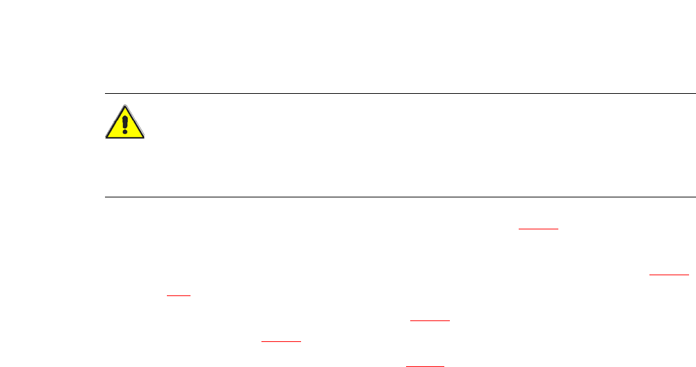
WARNING 6
Disconnect the docking station from the main power supply.
Disconnect the docking station from the compressed air supply
A second person will be needed to help with the conversion due to the weight of the component
trolley docking unit.
Loosen the two hexagon socket-head screws M8 x 18 (item 6 in fig. 6.5 - 4, page 419) and
remove the left-hand and right-hand guides (item 5 in fig. 6.5 - 4
).
6
Note: 6
Remove the covers (item 8 in fig. 6.5 - 4
) in the following cases only:
– You are converting the component trolley docking unit to a height of 830 mm.
– You are converting the component trolley docking unit from the height of 830 mm to a different
height.
Remove the 4 hexagon socket head screws M5x12. Hold the panel tightly so that it does not
drop down.
Remove the panel.
Loosen the 6 hexagon socket-head screws M8 (item 2 in fig. 6.5 - 4, page 419) and remove
the 6 washers.
Ask a second person to hold the component trolley docking unit, while you remove the 6
hexagon socket-head screws M8x40 (item 3 in fig. 6.5 - 4
).
Position the component trolley docking unit (item 7 in fig. 6.5 - 4) to the required height (item
1).
User Manual SIPLACE CA 6 Component and Die Handling
Edition 08/2011 EN 6.5 Docking Station for SIPLACE X Series Component Trolley
421
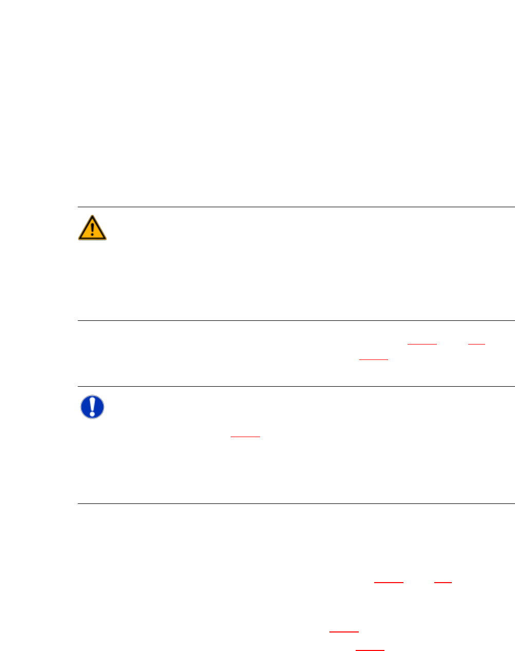
CAUTION 6
Be careful not to damage any cables while raising and lowering the component trolley docking
unit.
Insert the 6 hexagon socket-head screws M8x40 (item 3 in fig. 6.5 - 4) into the holes drilled
in the component trolley docking unit and docking station.
Fix the component trolley docking unit with the 6 M8 nuts and washers (item 2 in fig. 6.5 - 4,
page 419
).
Fasten the left and right guides (item 5 in fig. 6.5 - 4) with the hexagon socket-head screw
M8x18 (item 6 in fig. 6.5 - 4
).
If removed, refasten the covers (item 8 in fig. 6.5 - 4) with the 4 hexagon socket-head screws
M5x12.
6 Component and Die Handling User Manual SIPLACE CA
6.5 Docking Station for SIPLACE X Series Component Trolley Edition 08/2011 EN
422
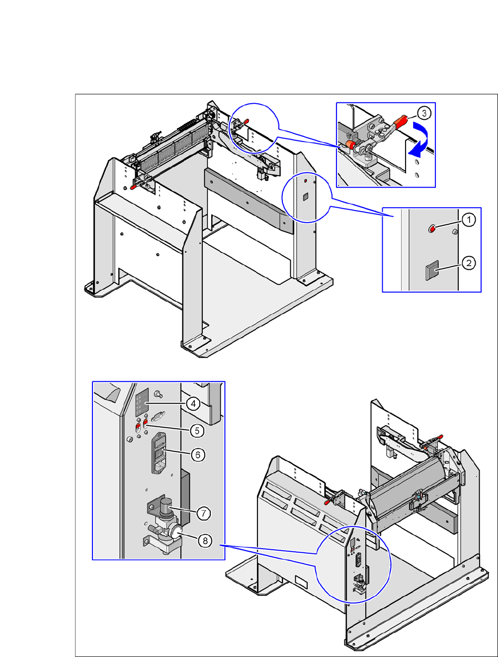
6.5.6 Controls and Displays
6
Fig. 6.5 - 5 Docking station - Controls and displays