00195941-03-UM SiplaceCA-EN.pdf - 第220页
3 Technical Data User Manual SIPLACE CA 3.12 Gantries Edition 08/2011 EN 220 The X axis essentially consists of the following main modules: – Gantry arm (1) – Head mo unt with X- axis linear mo tor (prima ry part) (2) – …
User Manual SIPLACE CA 3 Technical Data
Edition 08/2011 EN 3.12 Gantries
219
3.12.3 Structure of the X Axis
3
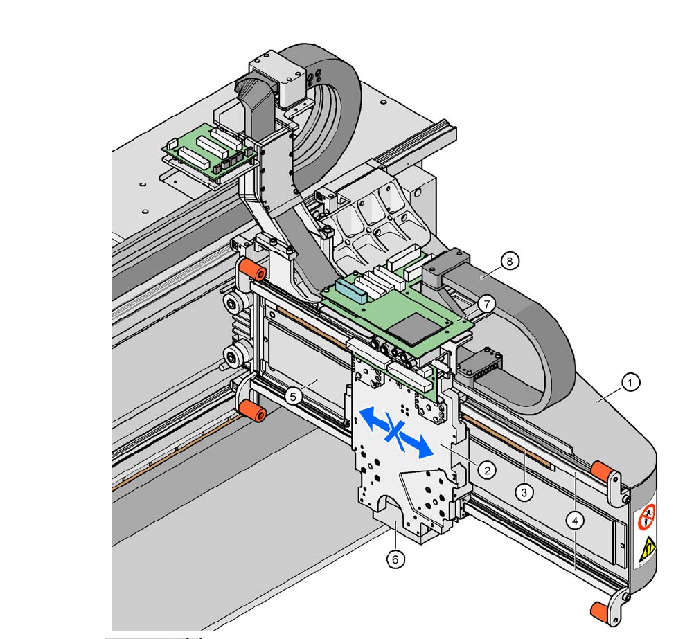
Fig. 3.12 - 3 Structure of the X axis
(1) Gantry arm
(2) Head mount with X-axis linear motor (primary part)
(3) Linear distance measuring system
(4) Guidance system
(5) Permanent magnet (secondary part of the X-axis linear motor)
(6) Sub-gantry camera
(7) Head boards
(8) Trailing cable

3 Technical Data User Manual SIPLACE CA
3.12 Gantries Edition 08/2011 EN
220
The X axis essentially consists of the following main modules:
– Gantry arm (1)
– Head mount with X-axis linear motor (primary part) (2)
– Linear distance measuring system (3)
– Guide system (4)
– Permanent magnet (secondary part of the X-axis linear motor) (5)
– Cable and hose carrier (8)
3
The head mount (2) holds the following components:
– Sub-gantry camera (PCB camera for the PCB vision module) (6)
– Set of head boards (7)
– Measuring head for the measuring system
– Collect&Place CA head or SIPLACE TwinHead
The gantry arm (item 1 in fig. 3.12 - 3
) is made of a carbon fiber compound, which makes the mod-
ules extremely light while, at the same time, being very rigid.
The X axis is driven by a linear motor. The secondary part of the drive consists of a permanent
magnet and is mounted on the gantry arm. The primary part is bolted to the head mount. The head
mount is designed to work with all placement head types - another reason for the high flexibility
achieved with SIPLACE placement machines.
3.12.4 Technical Data for the X Axis
3
Drive Direct, linear motor
Maximum speed 2.5 m/s
Travel range 480 mm
Distance measuring system Metal linear scale
Length of scale 520 mm
Resolution 1 µm
User Manual SIPLACE CA 3 Technical Data
Edition 08/2011 EN 3.12 Gantries
221
3.12.5 Structure of the Y Axis
3
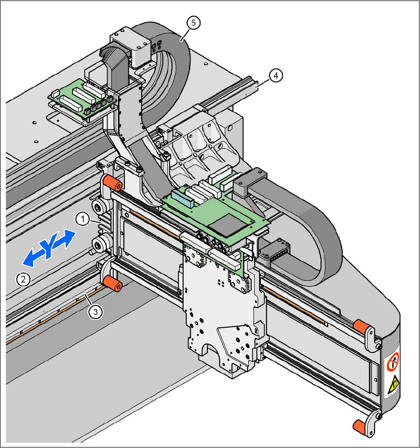
Fig. 3.12 - 4 Structure of the Y axis
(1) Y-axis linear motor (primary part)
(2) Permanent magnet (secondary part of the X-axis linear motor)
(3) Linear distance measuring system
(4) Guidance system
(5) Trailing cable