00196044-05 - sg x und x4i fse_en.pdf - 第102页
Communication and Control CAN Bus CAN Bus Protocol S tudent Guide (FSE) SI PL ACE X Series and X4I Communication and Control Edition 01/2009 EN 102 4.3.2 CAN Bus Protocol 4-12: CAN Bus Protocol Start This bit indicates…
Communication and Control
General Structure CAN Bus
Student Guide (FSE) SIPLACE X Series and X4I
Edition 01/2009 EN Communication and Control
101
4.3.1 General Structure
See also:
J
4.3.2 CAN Bus Protocol [
J
102]
J
4.3.2.2 CAN Bus Arbitration [
J
103]
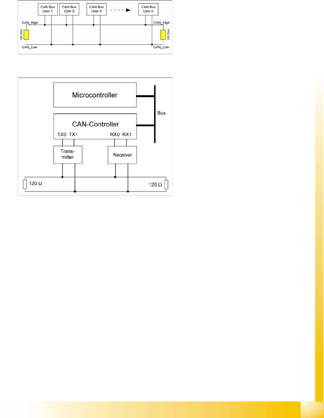
4-10: CAN Bus
The CAN Bus is a decentral multi-master bus. The
data are transmitted via the differential voltage of
the two CAN_High and CAN_Low lines, which are
each fitted with a terminating resistance of
120 Ohm.
4-11: CAN Bus controller and microcontroller
Legend
Microcontroller:
Exchanges data with the CAN controller
CAN controller:
Adds the data frame, establishes the
connection and manages errors.
Transmitter/receiver:
>Adjusts the level (driver levels)
Each bus node has a CAN controller, which can
transmit and receive data if the bus is free.
This CAN controller communicates with a
microcontroller. The microcontroller steers and
controls the relevant CAN bus nodes.
A CAN Bus node can only transmit if the bus is free
i.e. if there is no communication taking place with
other nodes. Access to the CAN BUS is fixed in the
CAN protocol (identifier). This results in differing
priorities among the individual CAN bus nodes.
Communication and Control
CAN Bus CAN Bus Protocol
Student Guide (FSE) SIPLACE X Series and X4I
Communication and Control Edition 01/2009 EN
102
4.3.2 CAN Bus Protocol
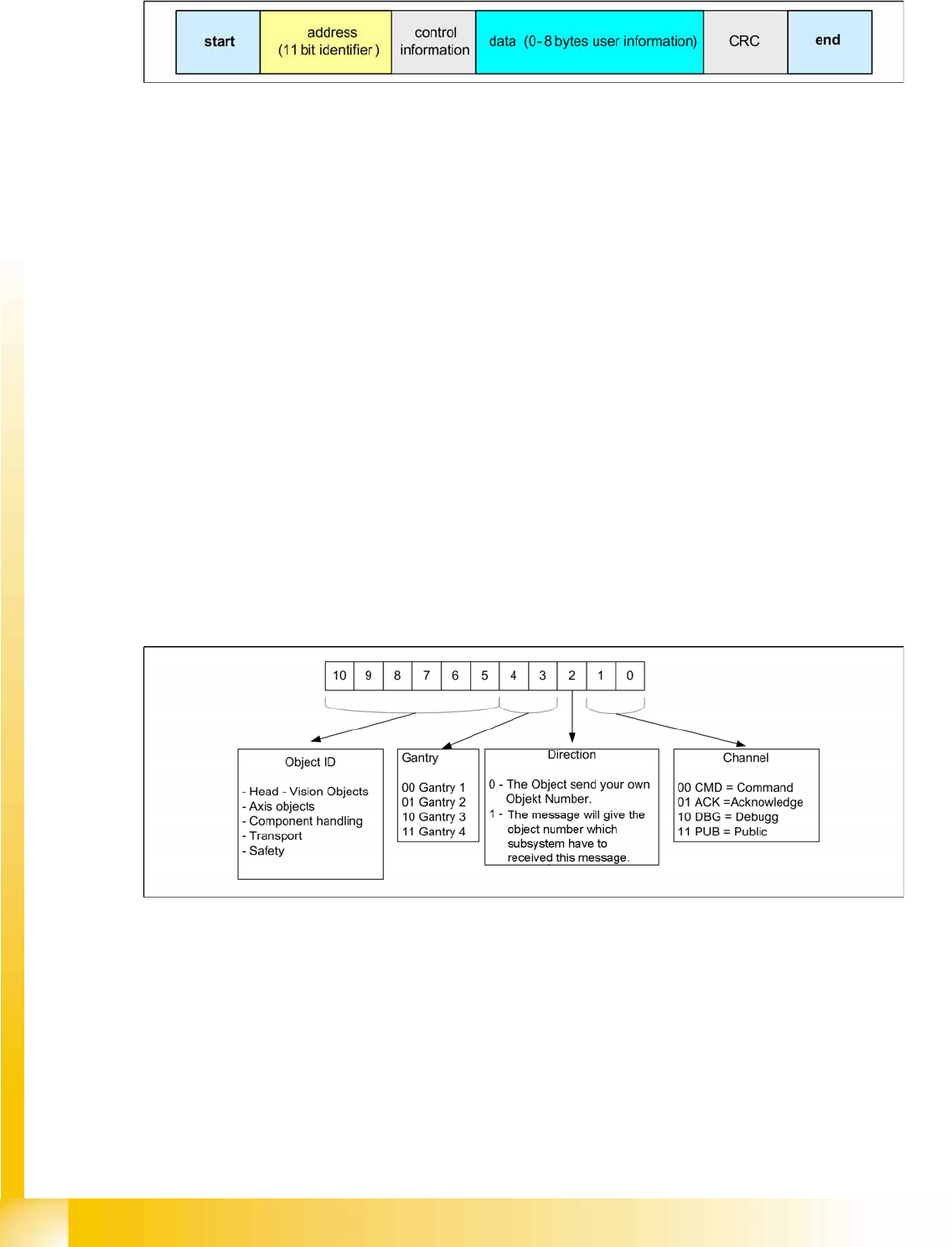
4-12: CAN Bus Protocol
Start
This bit indicates the beginning of a telegram and is a dominant bit. After this bit is set, no other user
of the CAN bus is able to send.
Address field (11 bit identifier)
The 11 bit address identifier value determines the bus access. The lower value has the highest
priority.
Control field
The 4 lowest bits in the 6 bit field show the data length of the following data field in bytes (DLC: Data
Length Code.
Data field
Contains the information actually required and can be from 0 byte to 8 byte. The transfer of a byte
begins with the most significant bit (the bit with the highest value).
Data control field CRC
Consists of a 15 bit check sequence (CRC sequence + CRC delimiter = CRC Field - Cyclic
Redundancy Check) and a recessive delimiter bit. The redundant information in the control
sequence allows the receiver to check whether the message received has been falsified by
interference.
End
Each data telegram is terminated by a sequence of 7 recessive bits.
4.3.2.1 11 Bit Identifier
4-13: 11 Bit Identifier
The CAN bus system is using the 11 Bit identifier for addressing the different CAN objects
An 11 Bit identifier (address) identifies the type, priority, source and /or target of the message.
This identifier also controls the bus access (arbitration).
Communication and Control
CAN Bus Protocol CAN Bus
Student Guide (FSE) SIPLACE X Series and X4I
Edition 01/2009 EN Communication and Control
103
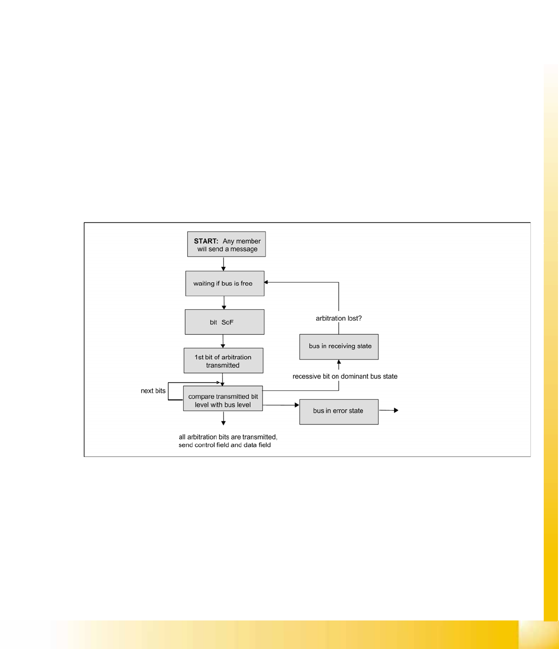
4.3.2.2 CAN Bus Arbitration
Arbitration (arbitration means decision)
In CAN networks, there is no addressing of subscribers or stations in the conventional sense, but
instead, prioritized messages are transmitted. Whenever the bus is free, any unit may start to transmit a
message. In general, a subscriber can only occupy the bus if this is free. The bus subscriber can detect
the bus occupation state by analyzing a certain time period within which the bus must be inactive.
When multiple nodes begin to send a message at the same time, a selection phase (arbitration phase)
is used to decide which node may remain on the bus.
Bus access conflicts are resolved by including a message arbitration field (as a default the 11 bit
identifier is used).
The basis of bit-wise arbitration is the differentiation of 2 physical bus levels, a dominant one (low) and
a recessive bit (high).
A free bus is always on the recessive level. A DATA FRAME prevails over the REMOTE FRAME. During
arbitration every transmitter compares the level of the bit transmitted with the level that is monitored on
the bus. If these levels are equal the unit may continue to send.
When a recessive level is sent and a dominant level is monitored, the unit has lost arbitration and must
withdraw without sending one more bit. At the end of arbitration, the only subscriber left on the bus is the
one whose message has the lowest identifier value (logical zero is a dominant level). The lower the
identifier value is, the higher the priority of a message is.
When the bus is free any unit may start to transmit a message. The message sent by this subscriber is
not destroyed here i.e. it is a loss-free arbitration.
4-14: Flow chart bus arbitration