00196044-05 - sg x und x4i fse_en.pdf - 第256页
C&P20A Reference Run for C&P20A Head Cleaning Cycle - Procedure S tudent Guide (FSE) SI PL ACE X Series and X4I C&P20A Edition 01/2009 EN 256 7.3.5 Cleaning Cycle - Procedure 7-13: Vacuum check procedure Th…
C&P20A
Z Axis Reference Run Reference Run for C&P20A Head
Student Guide (FSE) SIPLACE X Series and X4I
Edition 01/2009 EN C&P20A
255
7.3.3 Z Axis Reference Run
7.3.4 DP Axis Reference Run
The machine start procedure: After the DP master firmware is loaded the DP drives are initialized.
In the reference runs for the star axis, the DP drives rotate the segments into the 0° position again.
The DP axes can also be referenced independently of the star and Z axes.
By determination of the largest amplitude of the Hall sensor becomes the 0° position of the nozzle in
the factory (mechanically adjusted) and can't be changed.
The C&P head reference run has been successfully completed!
The gantry reference run follows – see Chapter Gantry
7-11: Z Axis Reference Run
The Z axis travels down to the zero point pulse of
the incremental encoder. After reaching the zero
pulse, the zero point correction is loaded. The Z
axis travels to the zero point correction value and
the position counter is set to 0 digits.
NOTE:
Station software startup initiates a
comparison of the Z and star axis zero
point correction values between the
head EPROM and the machine data. If
the zero point correction values are not
the same, recalculate the zero point
correction for the Z and star axes.
7-12: DP axis reference run
The DP axis rotates the nozzle into the correct
pickup angle and placement angle. After
component recognition has been performed, the
DP axis turns the components into the correct
placement angles and the determined correction
angle from the vision system.
C&P20A
Reference Run for C&P20A Head Cleaning Cycle - Procedure
Student Guide (FSE) SIPLACE X Series and X4I
C&P20A Edition 01/2009 EN
256
7.3.5 Cleaning Cycle - Procedure
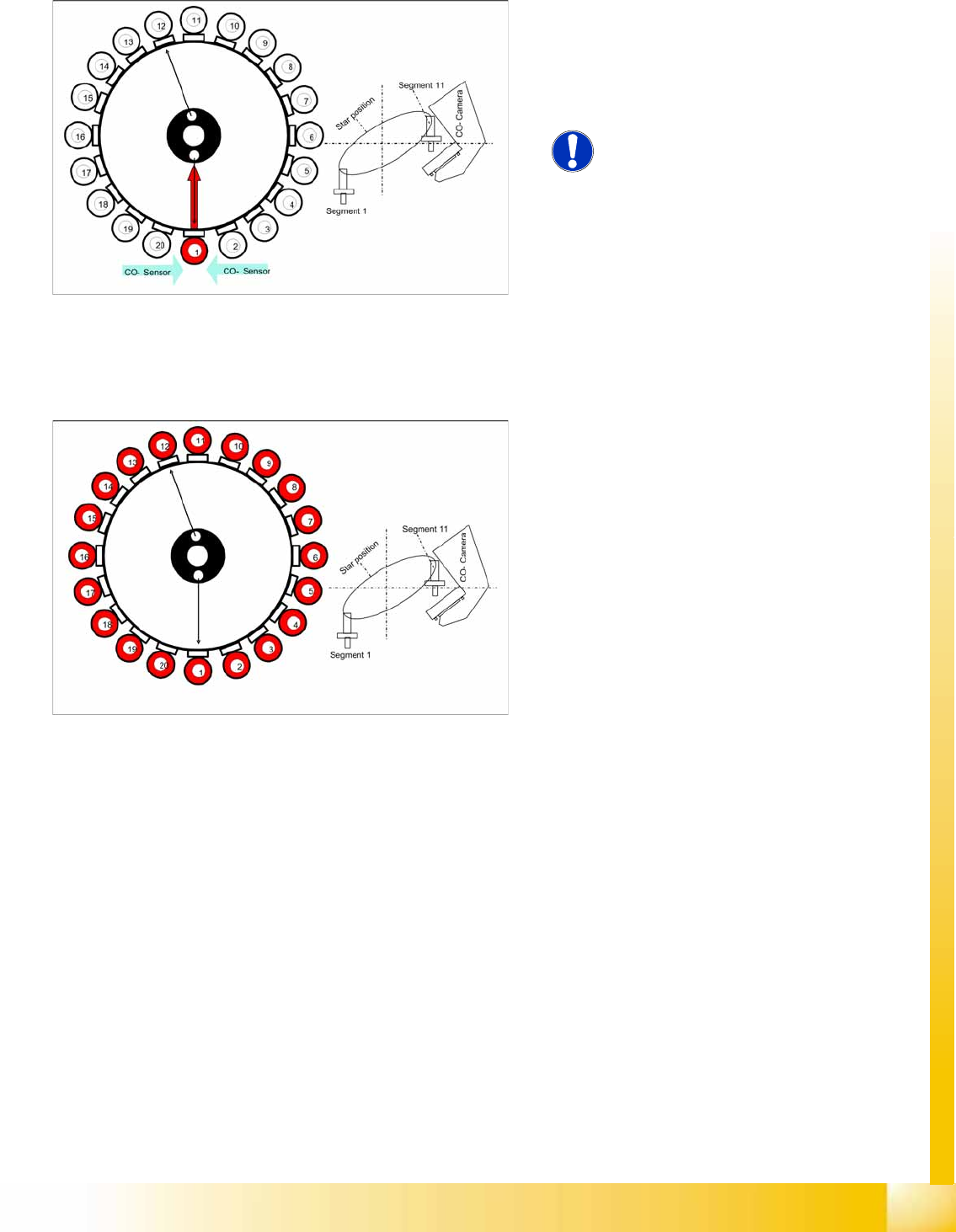
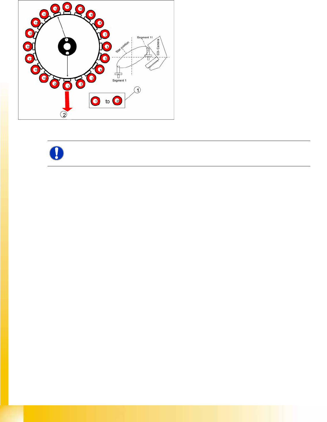
7-13: Vacuum check procedure
The gantry axes move the C&P head to the
reject position so that the nozzles can be
cleaned before the measuring cycle.
The Star axes move in an anticlockwise
direction and all cleaning functions are
performed at the same time, within one head
cycle.
1. The DP drives rotate each segment into the 0°
position.
2. The digital pressure control valve now
activates the air blast for the reject position.
The components still on the nozzle will be
rejected.
NOTE:
In SIPLACE X machines, components are rejected in the pickup/placement position.
C&P20A
Height Reference Run Reference Run for C&P20A Head
Student Guide (FSE) SIPLACE X Series and X4I
Edition 01/2009 EN C&P20A
257
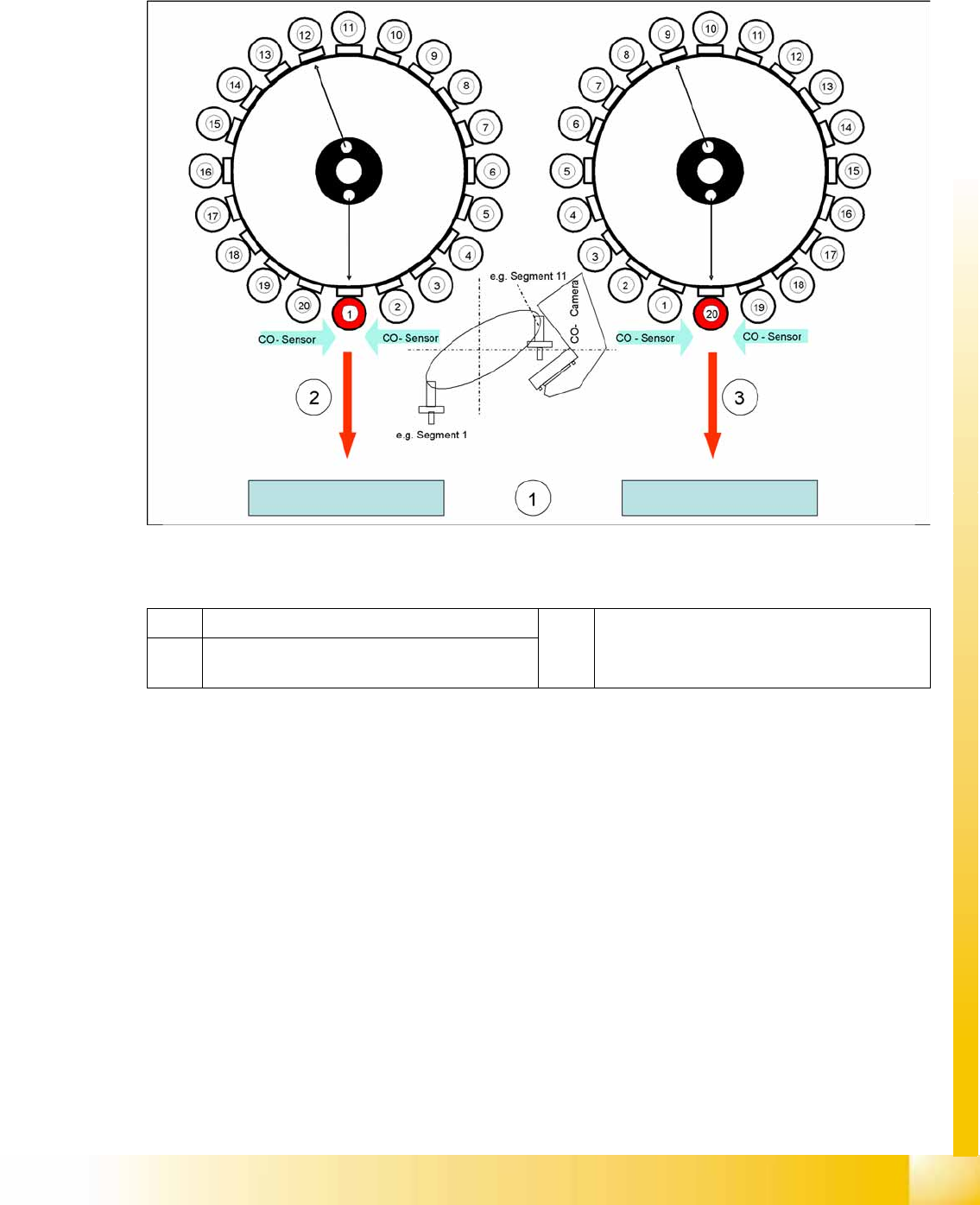
7.3.6 Height Reference Run
With this function we check the correct fitting of the nozzle on the sleeve and that the correct nozzle type
like the programmed one are set to the sleeves. The nozzle length is taken to calculate the pick up and
placement height for the subsequent placements.
7-14: Measuring the nozzle height
Legend
The gantry moves the placement head to the fixed conveyor side at height measurement position.
The star turns the segment for measuring into the pickup/placement position
The value "Vacuum open" is measured for each segment.
The Z axis is positioned downwards:
When the component sensor beam is interrupted, the Z position of the axis is determined for the
component sensor.
When the Z axis touches the conveyor side, the mechanical nozzle length is determined by the Z
position value and the closed vacuum value is measured.
The Z axis is positioned upwards:
When the component sensor beam is no longer interrupted, the Z position of the axis will be
measured again for the component sensor.
1 Top edge of the fixed conveyor side 3 Last step with segment 20 to measure the
nozzle length.
2 First step with segment 1 to measure the nozzle
length.