00196044-05 - sg x und x4i fse_en.pdf - 第81页
Overview Twin Head Overview of Components S tudent Guide (FSE) SIPL ACE X Series and X4I Edition 01/2009 EN Overview 81 3.2.10.2 Nozzle Changer for T win Head 3-28: Nozzle Changer for T win head SIPLACE X machines, equip…
Overview
Overview of Components Twin Head
Student Guide (FSE) SIPLACE X Series and X4I
Overview Edition 01/2009 EN
80
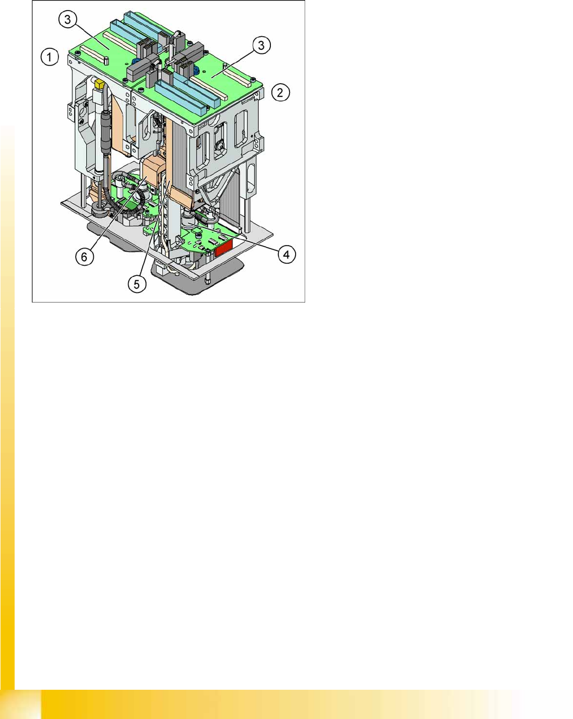
3.2.10 Twin Head
3.2.10.1 Description
3-27: Twin Head
Legend
1. Module 1
2. Module 2, rotate by 180 ° compared to module
1.
3. Main board on modul 1 and modul 2
4. D Axis
5. Linear motorZ Axis
6. Z axis incremental measurement system
The Twin head consists of two P&P heads of the
same model, which work according to the
Pick&Place principle. The second P&P head is
installed on the gantry, at a rotation of 180
degrees. One component after another can be
picked up per P&P, from the feeder module and be
optically centered by the stationary camera. On
the way to the placement position, the
components are rotated into the correct position.
They are then carefully positioned onto the board,
with great precision and with the help of a
regulated air blast and preset force.
Type 5xx nozzles are used for the Twin head.
Type 4xx nozzles for the P&P head and type 8xx
and 9xx nozzles for the C&P heads can be used
with an adapter.
Overview
Twin Head Overview of Components
Student Guide (FSE) SIPLACE X Series and X4I
Edition 01/2009 EN Overview
81
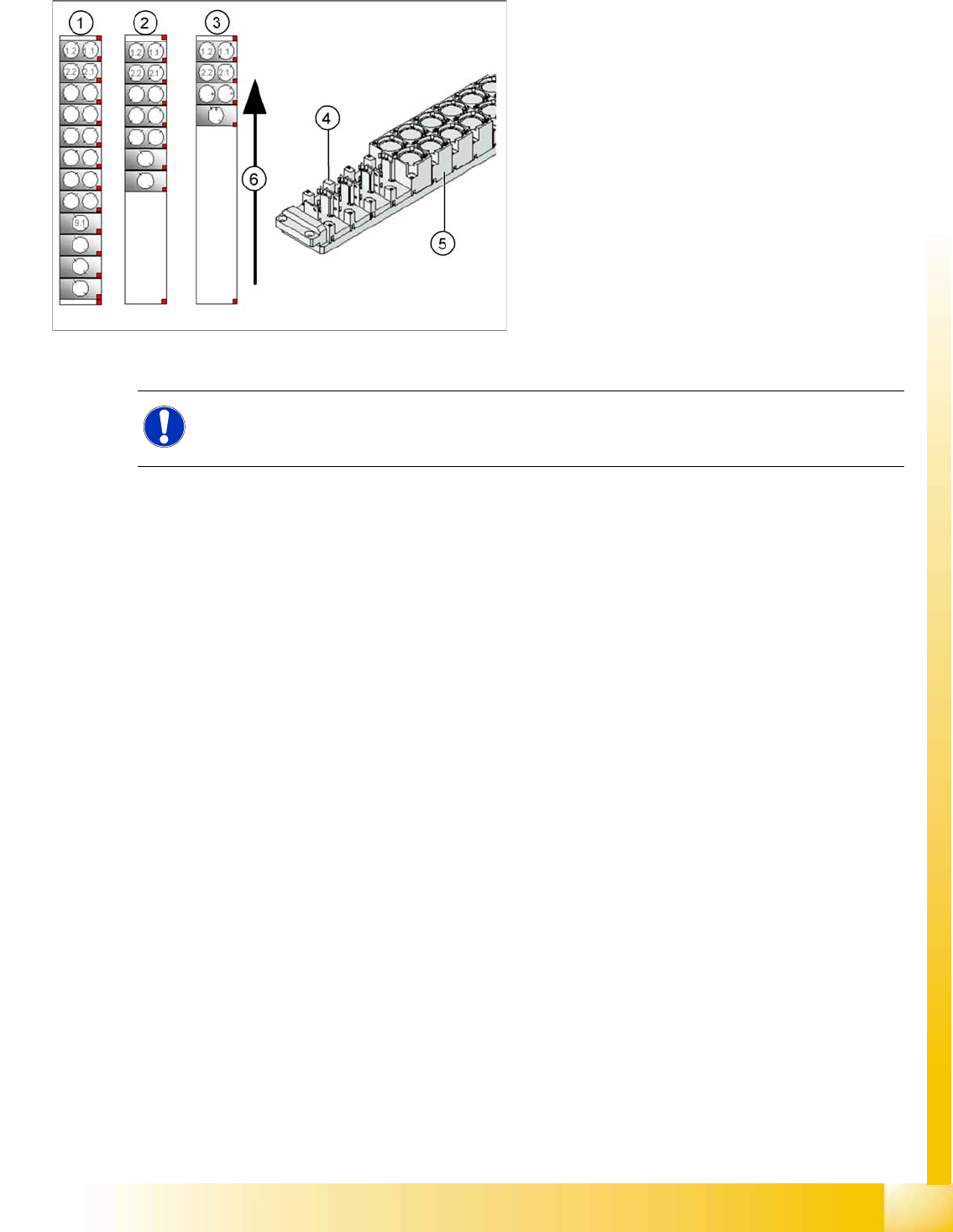
3.2.10.2 Nozzle Changer for Twin Head
3-28: Nozzle Changer for Twin head
SIPLACE X machines, equipped with a Twin head,
have one nozzle changer as a standard. This
nozzle changer is then installed in either sector 3
or sector 1.
The nozzle changer for a Twin head consists of a
standard module with 3 garages, each holding two
standard nozzles and one garage, holding one
special nozzle (see diagram).
Legend
1. Complete Nozzle changer
2. Extended Nozzle changer
3. Standard nozzle changer
NOTE:
If required, the above mentioned configurations can be changed and other magazines for
standard or special nozzles can be added individually.
Overview
Overview of Components CPP Head
Student Guide (FSE) SIPLACE X Series and X4I
Overview Edition 01/2009 EN
82
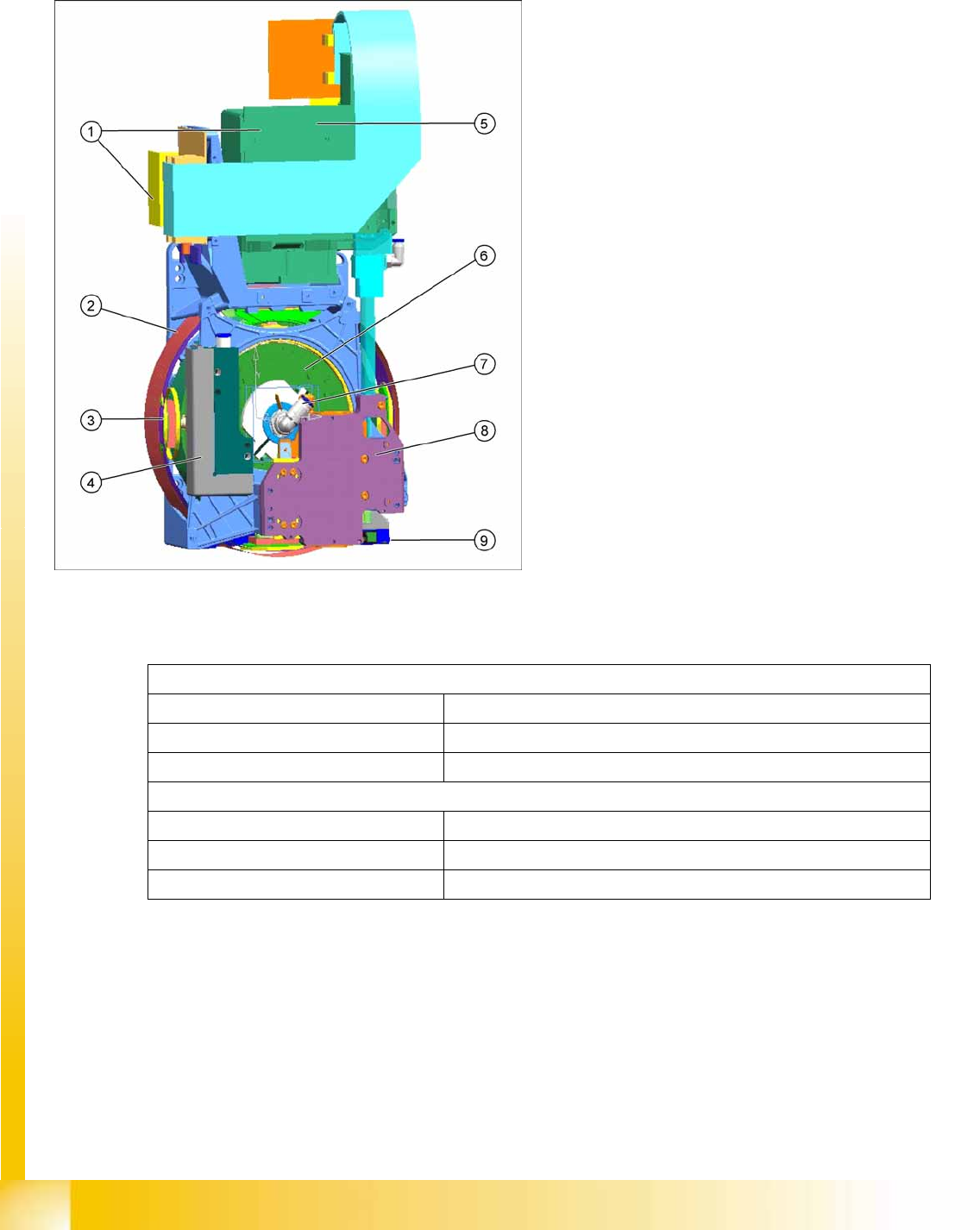
3.2.11 CPP Head
3.2.11.1 Overview
Technical Data
A mixed mode between Collect&Place and Pick&Place is also possible.
3-29: CPP head overview
CPP head (without component camera)
[03053528-xx]
Legend
1. Intermediate distributor 1 and 2
2. Star motor (integrated in head housing)
3. DP axis (as direct drive)
4. Pressure Control Valve
5. Component camera (standard: SST29)
6. Single Core Solution (SCS) – control DP
drives
7. Hold circuit with venturi nozzles and valve
terminal
8. Z axis with return cylinder
9. Component sensor in the pick and place
position
In Collect&Place mode
Component spectrum 01005 to 27x27 mm, up to 8.5 mm height
Speed Up to 24.000 cph
X/Y accuracy +/- 55 µm for 4 (sigma)
In Pick&Place mode
Component spectrum 01005 to 50x40 mm, up to 11.5 mm height
Speed Up to 1.500 cph
X/Y accuracy +/- 45 µm for 4 (sigma)