00196044-05 - sg x und x4i fse_en.pdf - 第221页
Gantry Mechanical Adjustment of the Incremental Encoder Settings S tudent Guide (FSE) SIPL ACE X Series and X4I Edition 01/2009 EN Gantry 221 6.3.3.5 Anticrash Function 6-11: Example of the anticrash f unction sequence i…

Gantry
Settings Anticrash Function for the A364 Axis Card
Student Guide (FSE) SIPLACE X Series and X4I
Gantry Edition 01/2009 EN
220
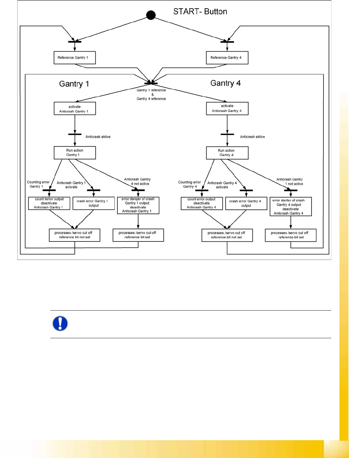
6.3.3 Anticrash Function for the A364 Axis Card
6.3.3.1 Anticrash Function for the A364
The anticrash function is no longer provided by the anticrash board but instead by the A364 software
(application 1). This means that the proximity switches used to monitor the travel range and the
sensor for monitoring the gantry spacing are no longer required.
Tasks:
– Monitoring the X and Y axis travel ranges
Evaluation of the actual position of the respective axis in the direction of the bumper, based on
the speed.
– Monitoring the distance of both Y axes in a placement area
Evaluation of the actual position of the own gantry and the partner gantry at gantry crash
monitoring.
– Count error monitoring of the gantry axis
Monitoring incoming count pulses (edge control) over time.
6.3.3.2 Anticrash Monitoring for the A364
The anticrash function is activated after the X/Y axes have been referenced. When the gantry axes are
referenced for the first time, anticrash monitoring is not active, which does not matter, due to the low
reference speed.
After this, the bit is set for the anticrash monitoring function and the actual position for the relevant
partner gantry is continuously communicated via the SPI Bus.
The following information is exchanged between the Y axes:
Actual position and speed of its own gantry
Status information (reference state, anticrash monitoring state ).
6.3.3.3 Error "Gantry Crash"
A “gantry crash” error is established by calculating the position difference and speed difference for both
axes. A gantry crash error is signaled via the axis card and the CAN Bus. The servo is released for both
axes and both need to be referenced again.
6.3.3.4 Count Error:
If the axis board detects a "fatal count error", the axis concerned will be released and the anticrash
function disabled. The other axis is informed of this in the status information and will also disable the
anticrash function. The released axis now needs to be referenced again,
after which the anticrash function will be re-enabled for both axes.
Gantry
Mechanical Adjustment of the Incremental Encoder Settings
Student Guide (FSE) SIPLACE X Series and X4I
Edition 01/2009 EN Gantry
221
6.3.3.5 Anticrash Function
6-11: Example of the anticrash function sequence in placement area 1
6.3.4 Mechanical Adjustment of the Incremental Encoder
The incremental encoders (read units) on the X and Y axis are adjusted mechanically to a distance of
0.4 mm +/- 0.1 mm to the incremental scale.
After this adjustment of the incremental encoder you have to check the zero pulse and track signals.
NOTE:
To set this distance, use one or more feeler gauges (small plastic disks) with a total thickness
of 0.4 mm.
Gantry
Track Signals and Zero Pulse Checking the Zero Pulse Signal
Student Guide (FSE) SIPLACE X Series and X4I
Gantry Edition 01/2009 EN
222
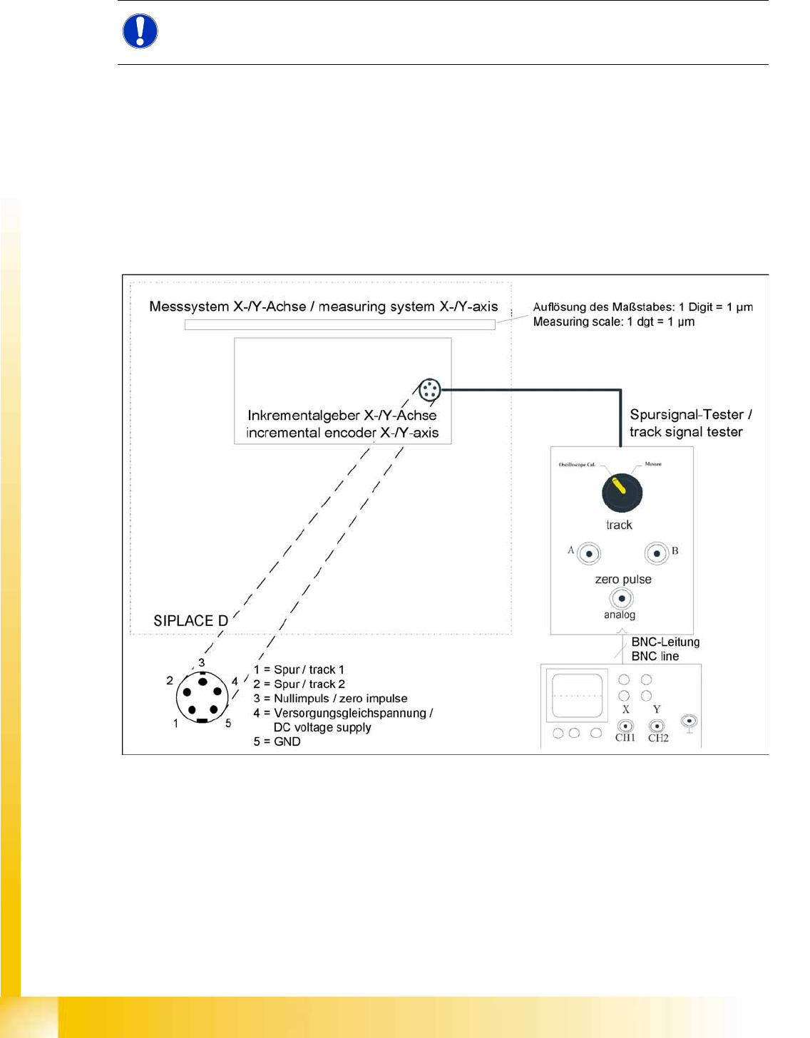
6.4 Track Signals and Zero Pulse
6.4.1 Checking the Zero Pulse Signal
The zero pulse must be reliably and clearly recognized by the read head. To ensure this, you can check
both the analog and the digital zero pulse. Electronically controlled settings can not be performed on the
incremental length measurement system.
See also:
J
4.4.1.2 Zero Pulse at the Track Signal Encoder [
J
131]
6.4.1.1 Measuring the Analog Zero Pulse Signal
6-12: Measurement procedure for checking the analog zero pulse and the analog track signals
NOTE:
Since 2007 a new read head is fitted. A larger measuring window allows you to reliably
compensate contaminants on the incremental scale (up to approx. 2.5 mm).