00196044-05 - sg x und x4i fse_en.pdf - 第464页
Modular Conveyor Conveyor Settings Conveyor Control TSP 301 S tudent Guide (FSE) SI PL ACE X Series and X4I Modular Conveyor Edition 01/2009 EN 464 1 1.3.10 Conveyor Control TSP 301 1 1.3.10.1 Jumper Settings for TSP 301…
Modular Conveyor
Checks After Mechanical Work on the Conveyor Conveyor Settings
Student Guide (FSE) SIPLACE X Series and X4I
Edition 01/2009 EN Modular Conveyor
463
11.3.8.2 Setting the Lifting Table Unit [00358684-05]
11.3.9 Checks After Mechanical Work on the Conveyor
Check: The distance between the top edge of the conveyor belt and the top stop should be 6 mm.
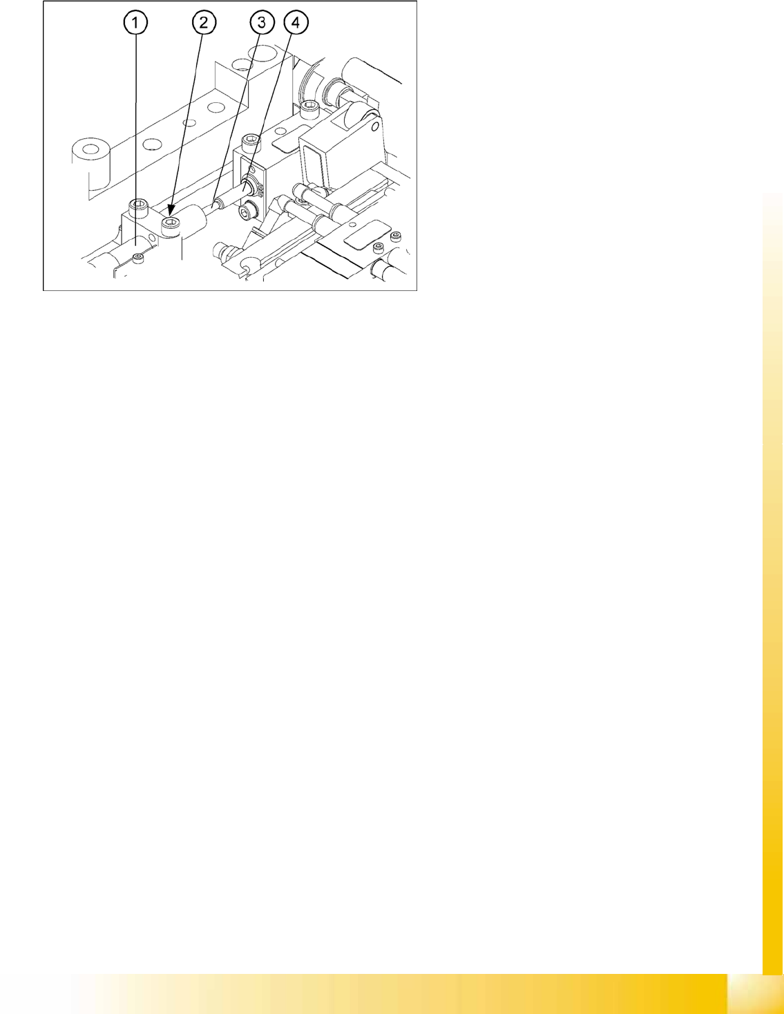
11-22: Setting the damping unit
The damping unit (1) allows the lifting table to
move gently upwards. When the PCB is clamped,
it also prevents excessive bounce by the PCB.
X Check whether the damping unit is fixed with
the locknut (2) in the mounting block and that
the plunger (3) of the damping unit is just
touching the actuator (4). In this default
setting, the lifting table should move up gently.
X If this is not the case, loosen the locknut at the
mounting block and turn the damping unit
approx. one rotation into the mounting block..
X Move the lifting table upwards, with the help of
the software.
X The lifting table should move gently upwards.
The PCB clamping should not engage audibly
and there should be no PCB clamping error
message.
X Check the speed of the lifting table and correct
where necessary.
Modular Conveyor
Conveyor Settings Conveyor Control TSP 301
Student Guide (FSE) SIPLACE X Series and X4I
Modular Conveyor Edition 01/2009 EN
464
11.3.10 Conveyor Control TSP 301
11.3.10.1 Jumper Settings for TSP 301
*Switches 1-2 set the hardware ID 5 for D4 machines and hardware ID 6 for X machines, HF and D3.
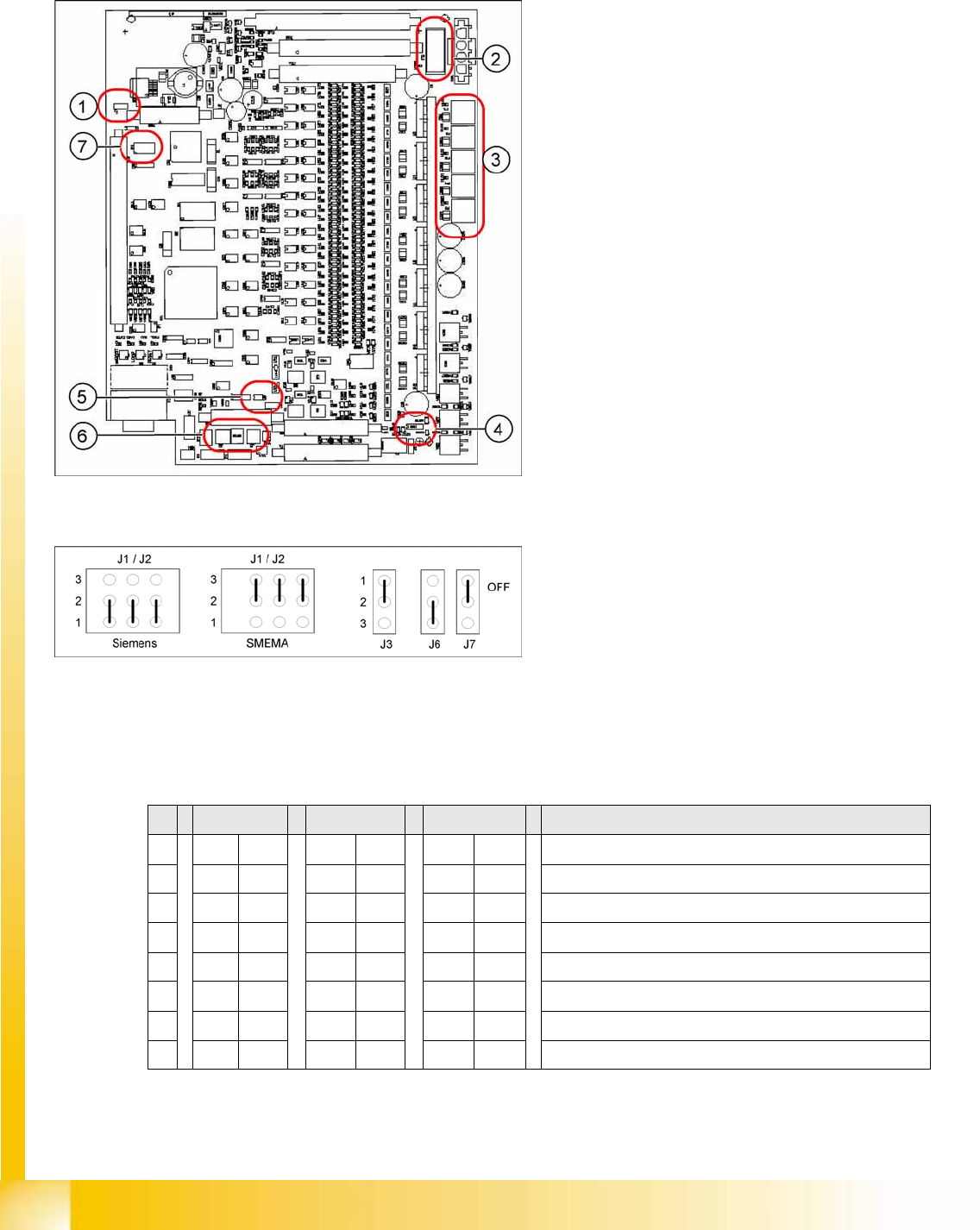
11-23: Jumper positions for conveyor control TSP 301
Legend
1. J7 CAN bus 1 terminating resistor
2. F6 Main Fuse TSP 301
3. F1 - F5 Fuses for the conveyor motors
4. J3 interference loop
5. J6 CAN bus 2 terminating resistor (not used)
6. J2, J1 downstream/upstream station
7. S4 DIL switch
11-24: Jumper J1, J2 "downstream/upstream station" at TSP 301
Legend
J1 upstream station
J2 downstream station
J3 interference loop (emergency stop on
productivity lift switches the placement
machine off)
J6 CAN bus 2 terminating resistor (not used)
J7 CAN bus 1 terminating resistor
S X4I D4 X/D3/HF Comments
1ON ON ONON*
2OFF ON OFF ON* = SIPLACE D4, OFF: SIPLACE X, HF, D3
3OFF OFF OFF OFF= clamping sensor is no longer used
4ONOFFOFFON = X4I, OFF: SIPLACE D4, X, HF, D3
5OFF OFF OFF Not in use
6 OFF ON OFF OFF OFF: Standard conveyor, ON: Quad lane
7OFF OFF OFF Not in use
8OFF OFF OFF Not in use
Modular Conveyor
Conveyor Control TSP 301 Conveyor Settings
Student Guide (FSE) SIPLACE X Series and X4I
Edition 01/2009 EN Modular Conveyor
465
11.3.10.2 Conveyor Control TSP 301 with Siemens Interface
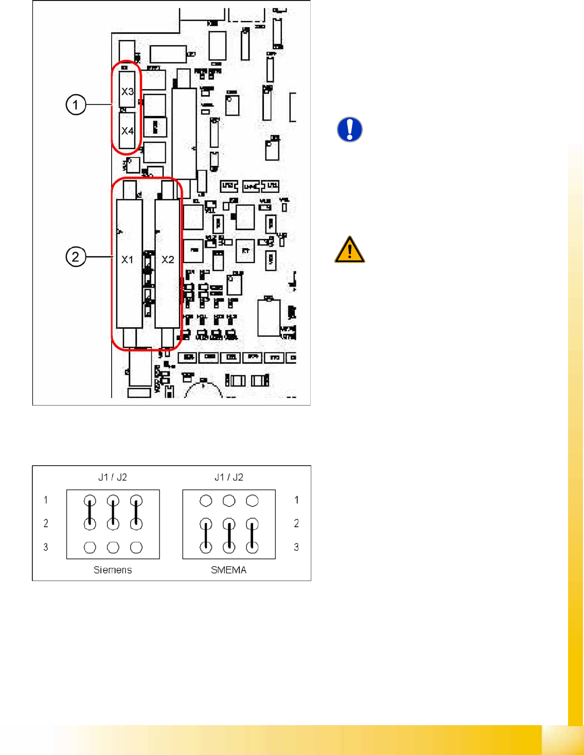
11-25: TSP 301 SMEMA --> Siemens
Legend
1. 10-pin plug for SMEMA interface
X3: upstream station
X4: downstream station
2. Connection for Siemens interface
X1: upstream station
X2: downstream station
NOTE: Standard / option
The SMEMA interface is the standard
and the Siemens interface optional for
all X machines.
The Siemens interface is the standard
and the SMEMA interface optional for
all D machines. An adapter is required
for the SMEMA interface when used on
D1/2/4 machines.
WARNING: Irreparable damage to the
TSP board!
The 10 pin Locking clip plug of SMEMA
connections must be disconnected
from the TSP 301!
Application: no modification.
Following modification are necessary for using the
Siemens interface:
X JumperJ1 / J2: need to be moved (see
following diagram).
X Disconnect the connector X3 and X4 on the
TSP 301!
X Connect the Siemens interface cable on the
connector X1 and X2.
11-26: Jumper J1 and J2 (Siemens/SMEMA)