00196044-05 - sg x und x4i fse_en.pdf - 第214页
Gantry Settings PCB Boards on the Gantry S tudent Guide (FSE) SI PL ACE X Series and X4I Gantry Edition 01/2009 EN 214 6.3.2 PCB Boards on the Gantry The printed cir cuit boards whic h are described in this chapter are b…
Gantry
Travel Ranges and Speed Monitoring Settings
Student Guide (FSE) SIPLACE X Series and X4I
Edition 01/2009 EN Gantry
213
6.3 Settings
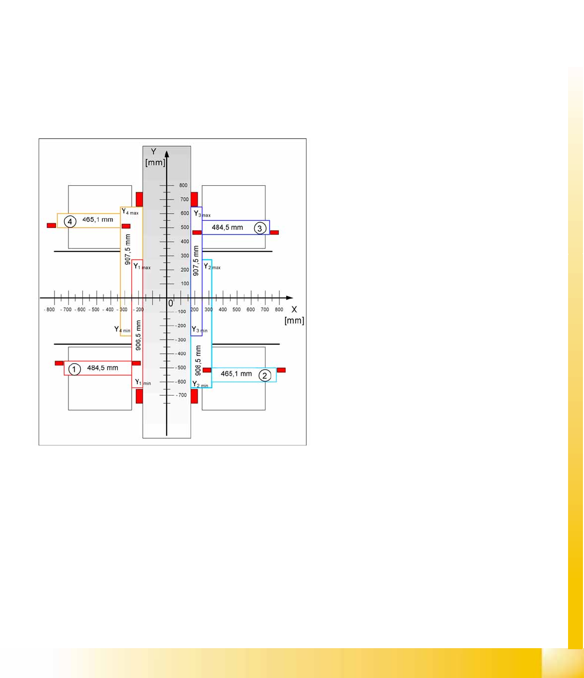
6.3.1 Travel Ranges and Speed Monitoring
The travel range of the X and Y axes will be determined during machine calibration.
This means that, during travel range calibration, the axis concerned moves as far as possible towards
the minimum or maximum position, until the set axis card target value is no longer reached. It is then
assumed that the hardware end position switch (bumper) has been reached. In a time window of approx.
10 ms, the greatest actual value achieved is taken to calculate the travel range.
To guarantee an appropriate safety gap before the hardware end switch is touched, a certain distance
is deducted from the set travel range. This enables the axis to brake in time, even when errors occur.
The X axis moves to the left and right bumper and measures their positions with a safety distance of 2.0
mm. The SW also deducts a value of 0.5 mm from the maximum or minimum travel range.
The Y axis only moves to its minimum position (gantry 1/2) or to its maximum position (gantry 3/4).
The position opposite is then calculated.
6-5: Travel ranges for X and Y axes (X4I)
Legend
1 - 4 = gantry 1 to 4
The end of the X axis travel range is + or -
0.5 mm before the software limit switch, which is
1.5 mm before the bumper. A safety distance of
2.0 mm to the bumper is adequate, if the X axis
moves into this area with excessive speed.
The end of the Y axis travel range is + or -
2.0 mm before the software limit switch. The Y
axis travel range for a particular placement area is
monitored in one direction by the software limit
switch and a bumper. In the other direction, there
is a permanent exchange of communication
between the axes and their positions, via the SPI
Bus (see description of the anticrash function).
Gantry
Settings PCB Boards on the Gantry
Student Guide (FSE) SIPLACE X Series and X4I
Gantry Edition 01/2009 EN
214
6.3.2 PCB Boards on the Gantry
The printed circuit boards which are described in this chapter are basically identical on each gantry and
do not depend on the head configuration. The gantry identification settings and the CAN bus terminating
resistance settings are defined at the DIP switch on the head interface.
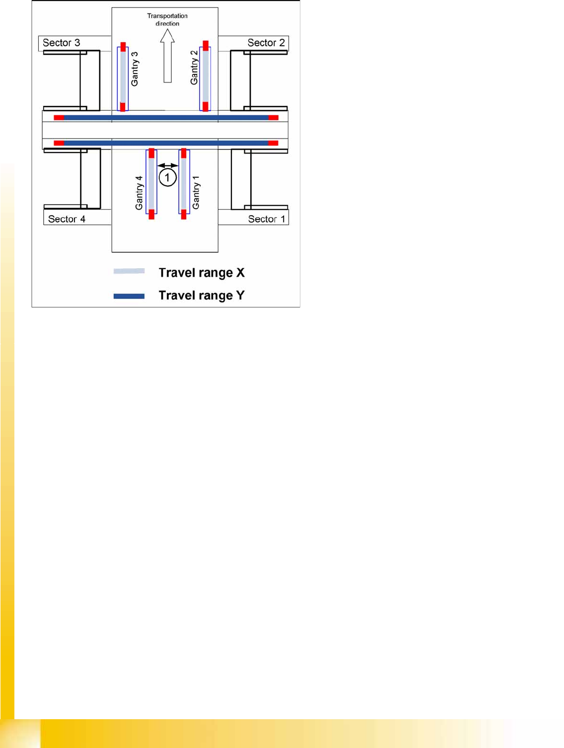
6-6: Travel ranges for X and Y axes
Legend
1. The minimum safety distance between the
gantries, during placement: minimum 4 mm.
Depending on the placement mode (i-placement
or alternating), the gantries will operate in one
placement area fully independently. This means
that one gantry does not need to know the position
of the other one.
Gantry
PCB Boards on the Gantry Settings
Student Guide (FSE) SIPLACE X Series and X4I
Edition 01/2009 EN Gantry
215
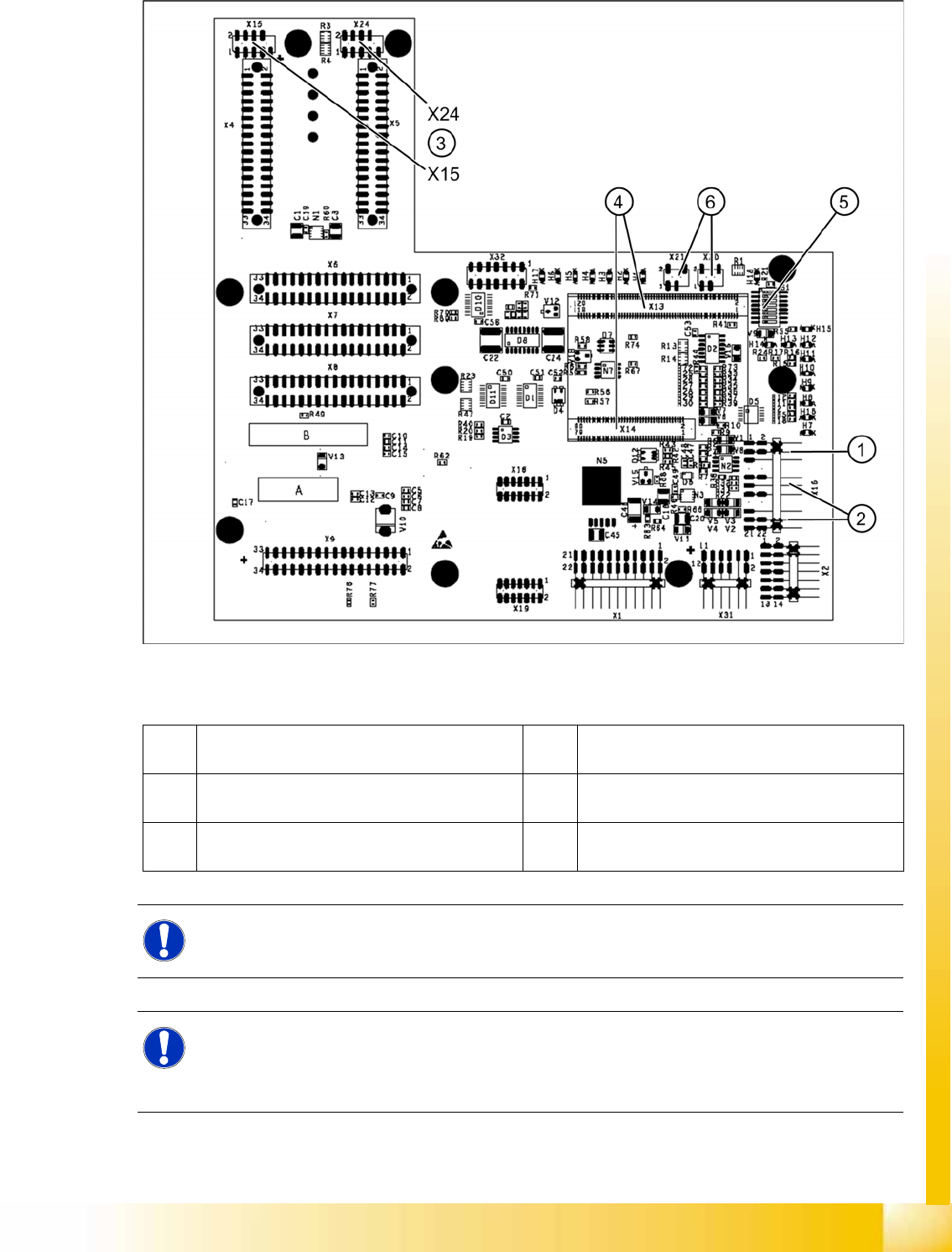
6.3.2.1 Head Interface C500
6-7: Head interface (C500)
Legend
1 X16 temperature sensor for X axis 4 X13 / X14 connector for 16 Bit processor board
(TQM module)
2 Proximity switches for X axis travel range (not
with A364)
5 DIP switch
3 X15 connector for incremental encoder X axis
(X24 connector digital track signals X axis)
6 X20/X21 both connections can be used for the
temperature sensors.
NOTE:
The DIP switch configuration for the gantry configuration is described in chapter Gantry.
NOTE: X4I
In SIPLACE X4I machines, a mirrored version of the C500 head interface is used on gantries 2
and 4.
X Note the different item number!