00196044-05 - sg x und x4i fse_en.pdf - 第373页
Twin Head Calibration of Vacuum Generator on the Twin Head Settings S tudent Guide (FSE) SIPL ACE X Series and X4I Edition 01/2009 EN T win Head 373 9.4.6.5 Checking the Air Blast SITEST: X Start SITEST and move the gant…
Twin Head
Settings Calibration of Vacuum Generator on the Twin Head
Student Guide (FSE) SIPLACE X Series and X4I
Twin Head Edition 01/2009 EN
372
9.4.6.2 Checking the Zero Calibration
SITEST:
X Select
Twin Head
X Select
Head Board
X Select
Measure Pressure
The zero calibration is performed with disabled vacuum and air blast (see Section (9.4.6.1 Zero Calibra-
tion of Vacuum Generator
J
371 ) ).
9.4.6.3 Calibrating the Closed Vacuum
SITEST:
X Select
Twin Head
X Select
Calibration functions
X Select
Calibrate closed vacuum
9.4.6.4 Checking the Pressure Tightness of the Vacuum System
X Start SITEST.
X Move the gantry so that you can easily reach the nozzle with one and the keyboard with the other
hand.
SITEST:
X Select
Twin Head
.
X Select
Head Board
.
NOTE:
The pressure deviation to the ambient pressure at 0 - mbar (zero calibration) should not exceed
+/-10 mbar.
NOTE:
The value "Vacuum closed" is measured and stored for both Twin modules.
A dialog box shows the old and the new values.
NOTE:
The term "closed vacuum" corresponds to "threshold value closed".
Twin Head
Calibration of Vacuum Generator on the Twin Head Settings
Student Guide (FSE) SIPLACE X Series and X4I
Edition 01/2009 EN Twin Head
373
9.4.6.5 Checking the Air Blast
SITEST:
X Start SITEST and move the gantry so that you can easily reach the nozzle with one hand and the
keyboard with the other hand.
X Select
Twin Head
X Select
Head Board
X Select the appropriate Twin module.
X Switch "on" the air blast.
X Close the nozzle of the appropriate segment (e.g. by sealing it with your finger tip).
X You can edit and modify the value for the air blast pressure or leave the standard value.
X Select
Measure Pressure
.
X The measured value should correspond (approx.) with the given value.
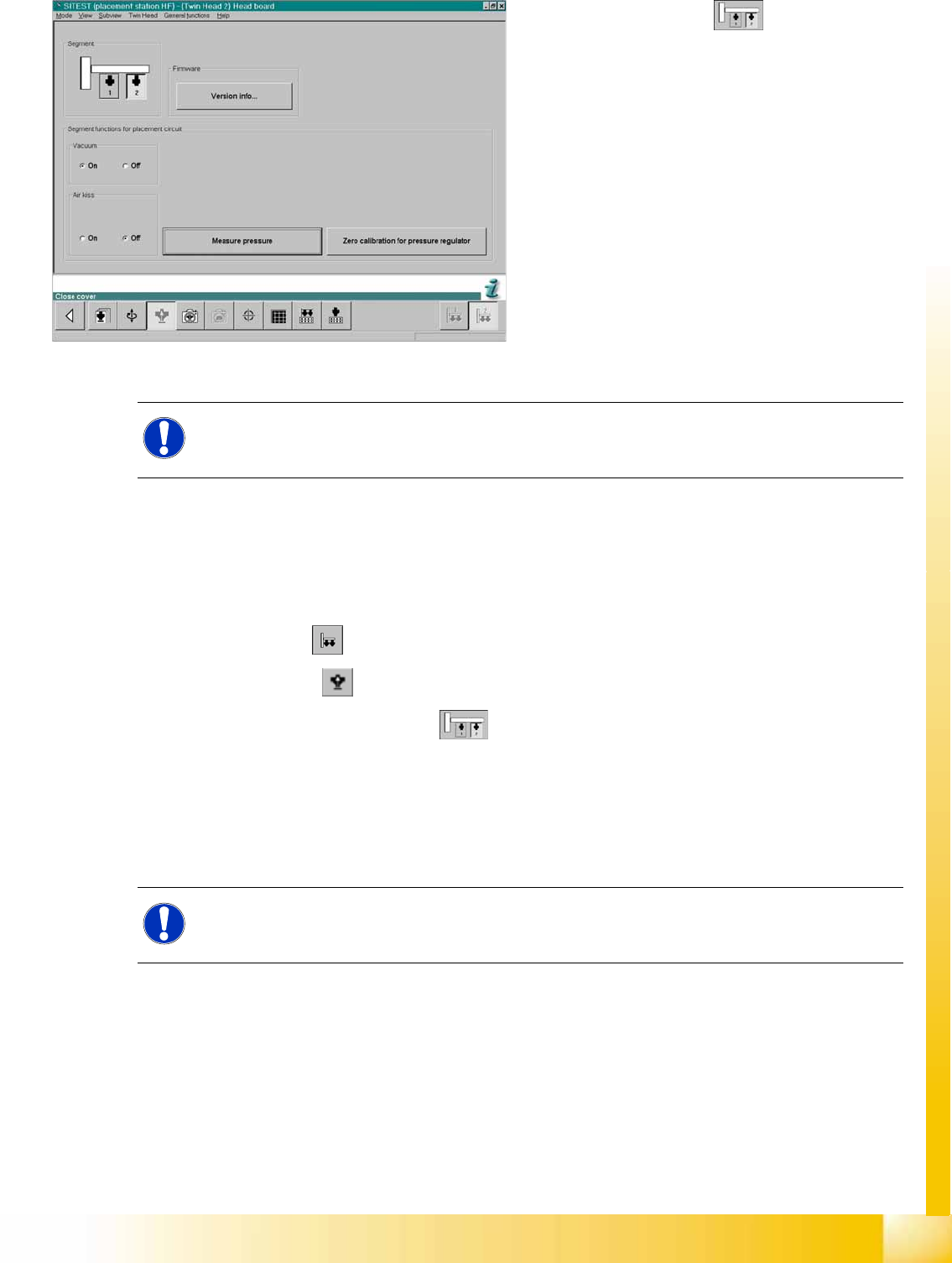
9-17: SITEST functions - head board
X Select the
Segment
.
X Switch the vacuum on and the air blast off.
X Close the nozzle of the appropriate segment
(e.g. by sealing it with your finger tip).
X Select
Measure Pressure
.
X The displayed value should be close to the
"Threshold value closed".
NOTE:
The value "vacuum closed" is determined in the
Calibrating the Twin head
==>
Calibrate
closed vacuum
.
NOTE:
The air blast value can be edited to a value between 0 and 400 mbar, with the Siemens Service
password. Default setting: 400 mbar
Twin Head
Settings Calibrating the Twin Head
Student Guide (FSE) SIPLACE X Series and X4I
Twin Head Edition 01/2009 EN
374
9.4.7 Calibrating the Twin Head
During initial setup or after replacement of a Twin module the Twin Head must be calibrated. This menu
measures the offset between the Twin segment and the PCB camera center.
X Put the nozzles 517 by hand on the segments of the P&P modules.
X Make sure that the first nozzle from the garages are empty and depend on this the filling level from
the nozzle changer are edited, This is necessary for calibration of the pickup height.
X Enter the nozzle "517" for both TWIN modules as active nozzle on the TWIN Head:
SITEST:
X Select
Twin Head
X Select the nozzle changer head function.
X Select the appropriate "segment" from the list.
X Select
Edit
==>
517
and
Accept
.
X Enable
Select Segment
.
X Select
Confirm Exchange
.
X In the SITEST main menu, select
All Heads and Cameras
X Only select the checkbox
Twin Head
of the applicable placement area.
X Select
Start
.
9.4.8 Mechanical Adjustment of the Z Axis Incremental Encoder
9.4.9 Vision DC/DC Converter
The function of the Vision DC/DC converter is to provide the 42V voltage supply for the stationary
cameras.
The 42V are use for the illumination of the stationary cameras.
When replacing the Vision DC/DC converter, observe the following settings, which depend on your
installation location (main/subdistributor).
9.4.10 Manual Lowering of Z Axis
The Twin head is designed for a placement force of 0.5 to 15 N (up to 30 N for the high force Twin head)
. The rotary axis needs to be very smooth-running, especially for low placement forces. Therefore, the
rotary axis is not constructed for traction forces.
NOTE:
The following calibration steps are performed automatically: - MA zero point, PCB camera,
calibration tool position, head height, TH calibration offset module 1 and 2, IC camera, (option
FC camera), nozzle changer.
NOTE:
The incremental encoder on the Z axis must be adjusted to a distance of 0.4 mm to the
incremental scale. Please adjust the incremental encoder parallel to the incremental scale.
After fitting, check the Z axis track signals (see Section Component Handling).
Main distributor Subdistributor
Bypass 1 (wire jumper) 10 - 13 6 - 13
Bypass 2 (wire jumper) 11 - 12 4 - 12