00196044-05 - sg x und x4i fse_en.pdf - 第162页
Communication and Control Board IDs Reading the Board IDs out of the EEPROM S tudent Guide (FSE) SI PL ACE X Series and X4I Communication and Control Edition 01/2009 EN 162 Assembly ID 01 is digita l pressure control val…
Communication and Control
Reading the Board IDs out of the EEPROM Board IDs
Student Guide (FSE) SIPLACE X Series and X4I
Edition 01/2009 EN Communication and Control
161
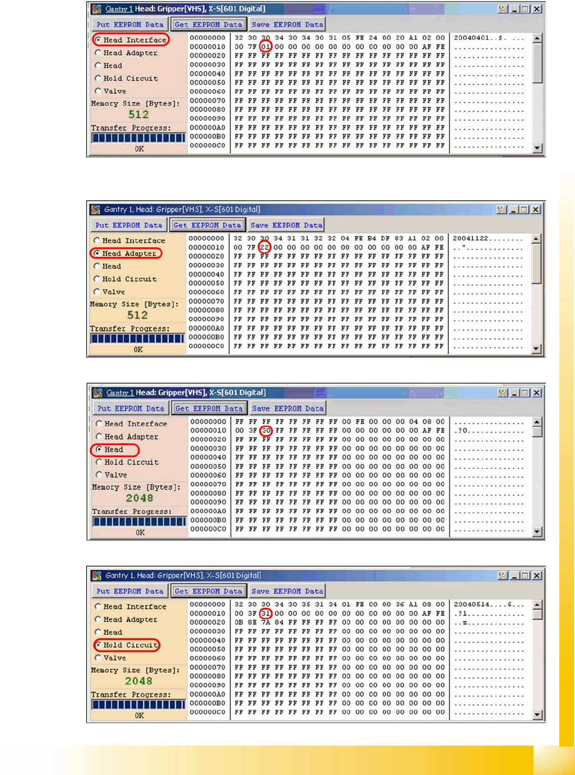
4-61: Head interface board type recognition ID 01
X The ID will appear in the
memory cell
12, the ID 01 for the head interface C500.
4-62: Head adapter board type recognition ID 22 for the C&P20A head
4-63: C&P20A board ID 30
4-64: C&P20A board ID 31 vacuum sensor, hold circuit
Communication and Control
Board IDs Reading the Board IDs out of the EEPROM
Student Guide (FSE) SIPLACE X Series and X4I
Communication and Control Edition 01/2009 EN
162
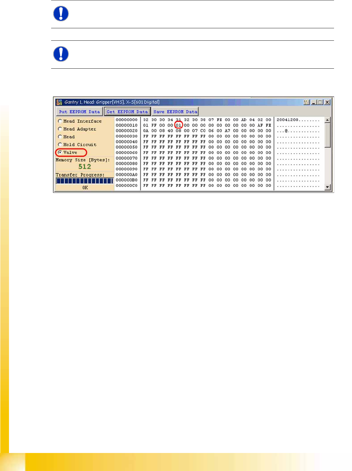
Assembly ID 01 is digital pressure control valve
Assembly ID 02 is analog pressure control valve
4-65: Device number pressure control valve digital C&P20A
NOTE:
The digital pressure control valve (C&P20A) and the analog pressure control valve (Twin head)
do not have a board ID or it is currently 00.
NOTE:
Both pressure control valves will be recognized via a device number. This assembly ID is at
memory cell 14 in the EEPROM.
Communication and Control
Reading the Board IDs out of the EEPROM Board IDs
Student Guide (FSE) SIPLACE X Series and X4I
Edition 01/2009 EN Communication and Control
163
4.6.2.2 Reading and Writing the Board IDs with CAN Commands
X Switch off the machine.
X Connect the service laptop to the machine CAN bus at PA1 and/or PA2.
Make sure that the cable is connected at channel 1 for PA1 and at channel 2 for PA2 of the Kvaser
card.
X Switch on the machine
X Start the
Caccia
software and check the machine configuration in
Caccia
.
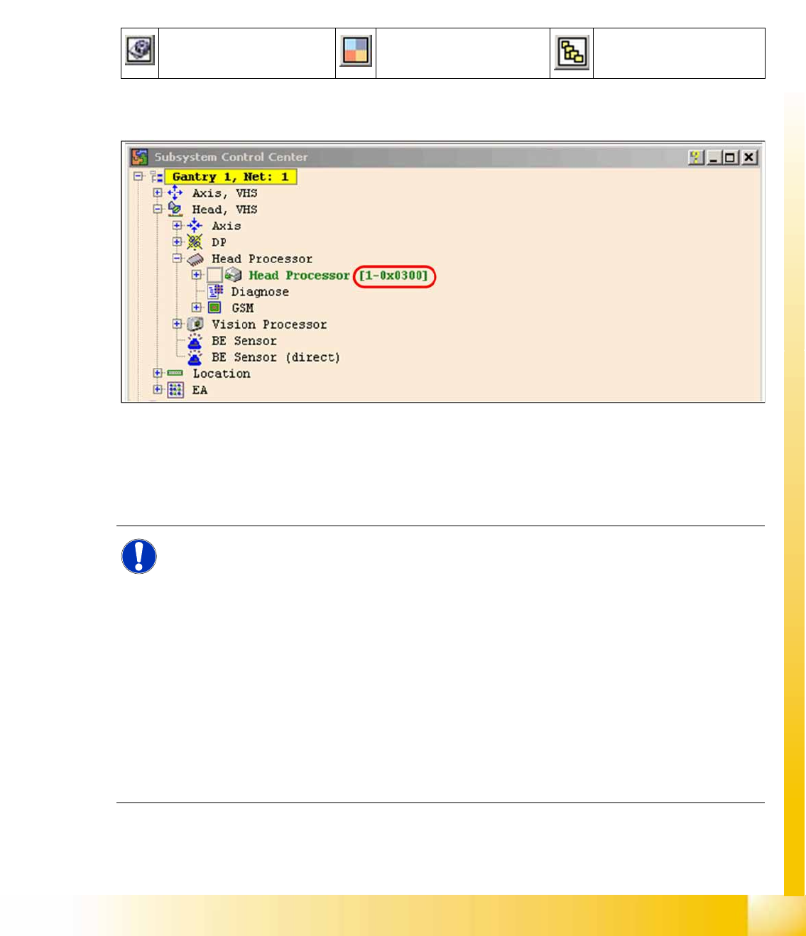
X Doubleclick on the
Open Subsystem Control Center
.
X Select
Get Versions
.
All available subsystems will be shown with their firmware versions and their CAN IDs.
4-66: Subsystem control center
X In the
Subsystem control center
window, search for the subsystem (TQM module), which you want
to access, in order to then use the correct CAN ID in the network window.
X This means, to check the head interface, head adapter and intermediate distributor use the CAN ID
300 for gantry 1 or 308 for gantry 2 and so on.
Change Properties Change Machine
Configuration
Open Subsystem Control
Center
NOTE:
Always use the IDs which are shown in the subsystem control window, when you click on
GET VERSION or ACTIVATE IDs
.
e.g. Head Processor
Gantry 1 -->
300
Gantry 2 -->
308
Gantry 3 -->
310
Gantry 4 -->
318
.
Exception: If you don‘t received a message from a subsystem, so you can try to work with
"Standard ID‘s" e.g.Head processor:
Gantry 1 -->
304
Gantry 2 -->
30c
Gantry 3 -->
314
Gantry 4 -->
31c
,
required when two board IDs are missing.