00196044-05 - sg x und x4i fse_en.pdf - 第282页
C&P20A Settings Setting the Jaws for C&P20A S tudent Guide (FSE) SI PL ACE X Series and X4I C&P20A Edition 01/2009 EN 282 7.5.4 Setting the Jaws for C&P20A 7.5.4.1 Basics The jaws need to be correctly set…
C&P20A
Setting the Nozzle Changer for C&P20A Settings
Student Guide (FSE) SIPLACE X Series and X4I
Edition 01/2009 EN C&P20A
281
7.5.3 Setting the Nozzle Changer for C&P20A
7.5.3.1 Nozzle station
The height of the nozzle reject unit must be set to 140.0 +\-0.3 mm. Measurement follows the same
procedure as that for the nozzle changer .
See also:
J
7.5.3 Setting the Nozzle Changer for C&P20A [
J
281]
J
7.5.3 Setting the Nozzle Changer for C&P20A [
J
281]
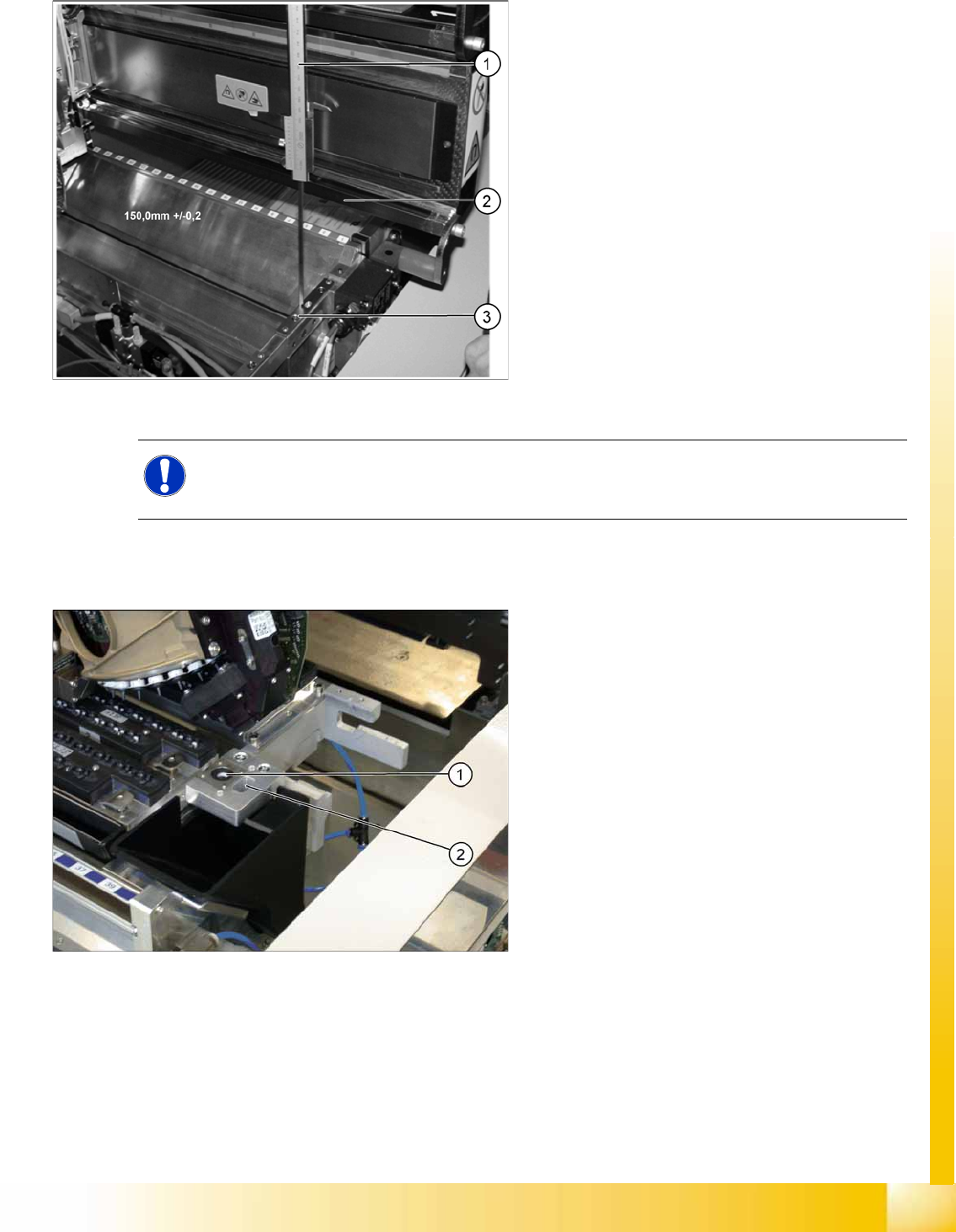
7-45: Setting the nozzle changer for C&P20A
Legend
1. Measuring scale
2. Top edge of the X axis lower linear guide
3. Fitting surface for nozzle changer
In order to guarantee the safety gap between the
head (component sensor) and nozzle changer, the
contact surface of the nozzle changer on the
docking unit is set to a distance of 150.0 mm +/-
0.2 mm to the X axis linear guidance, with a
measuring scale. The height of the fitting surface
on the docking unit is adjusted with the help of
shim rings. The nozzle changer can then be fitted.
NOTE: Fitting the nozzle changer
When fitting the nozzle changer, make sure that the component reject tray can be removed and
Ensure that the screws you are using are not too long, as these might jam the reject tray.
The C&P20 reject unit is equipped with a device
for checking the seat of the nozzles on the
segments, after a nozzle change. The nozzle
station also features an air blast valve, which
removes the components externally with a blast of
air. If components are not rejected via the blast air
pulse by the pressure control valve, the placement
head will automatically move to the nozzle station
to reject the components there.
Legend
1. Check nozzle seat
2. Nozzle reject
C&P20A
Settings Setting the Jaws for C&P20A
Student Guide (FSE) SIPLACE X Series and X4I
C&P20A Edition 01/2009 EN
282
7.5.4 Setting the Jaws for C&P20A
7.5.4.1 Basics
The jaws need to be correctly set, to ensure that the bridge between the raceway and jaws is accurate.
The correct height between the raceway and jaws is achieved by determining the zero point correction
value for the Z axis.
When fitting the jaws at the Z axis, it is possible to rotate the jaws. With the help of the setting gauge,
the correct angle of the jaws to the raceway can be fixed.
When could you need to set the jaws?
When error messages are issued by the station software (e.g. reference run).
If the determination of the Z and star zero point correction is not successful, you will need to have
the position of the jaws checked by the Siemens Service team.
When replacing or dismantling the Z drive unit, as the jaws are not aligned to the raceway.
When dismantling the component sensor and star carrier
NOTE:
This service task requires the use of a special tool and may therefore only be performed by
specially trained service technicians from SIEMENS. The procedure is described in a separate
manual.
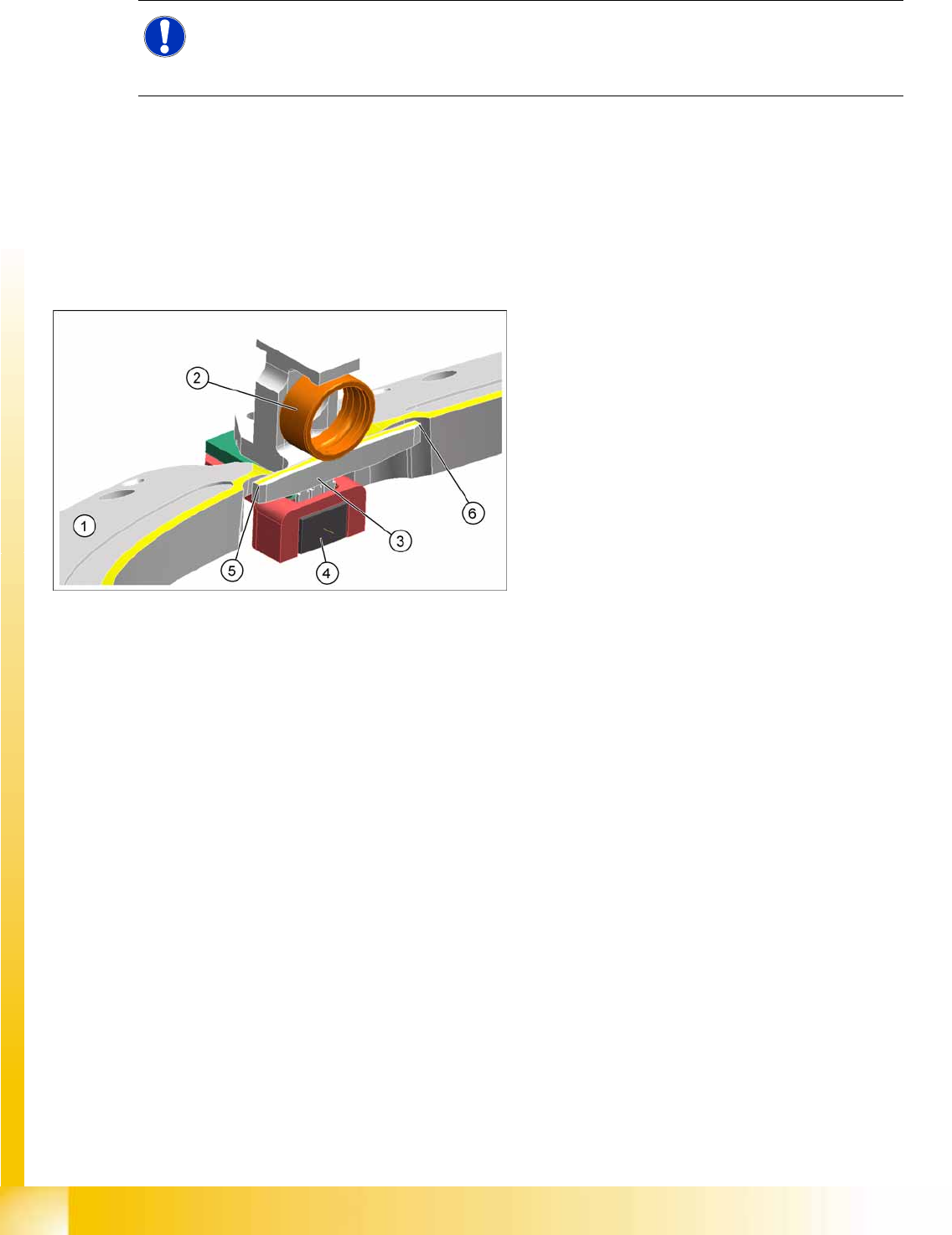
7-46: Raceway with Z axis
Legend
1. Raceway
2. Ball bearing on segment
3. Snap jaws
4. Light barrier down
5. Bridge raceway – jaws, left
6. Bridge raceway – jaws, right
C&P20A
Nozzle Changer for C&P20A Nozzle changer
Student Guide (FSE) SIPLACE X Series and X4I
Edition 01/2009 EN C&P20A
283
7.6 Nozzle changer
The nozzle changer enables the nozzle configuration to be changed quickly, thus allowing the placement
head to be quickly adapted to the needs of the placement process.
7.6.1 Nozzle Changer for C&P20A
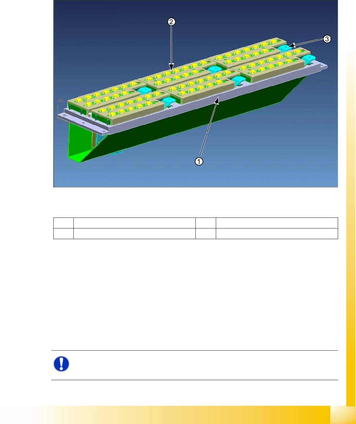
7-47: Main view - nozzle changer and nozzle magazine C&P20A
Legend
The new nozzle changer carrier can be used for both the C&P20A and the CPP heads, with the
corresponding magazines. Therefore, the nozzle changer does not need to be exchanged for the head
modularity between the C&P20A and CPP head.
The nozzle changer consists of six magazines, each with twelve nozzle garages. Each nozzle garage
can be configured with different nozzle types. Each magazine is clamped on the basic nozzle changer
body with 4 push buttons and two centering pins. The nozzle magazines are opened or closed with the
help of the pneumatic valves. Each magazine can be individually released and removed by pressing the
lever (one on each magazine). There are three microswitches beneath each magazine. These monitor
the correct position and correct magazine type. If all magazines have correctly engaged on the basic
body, this will be shown by a green LED. Since this microswitch is integrated into the safety circuit, the
machine can not be started unless the magazines are installed.
1 Nozzle changer basic unit 3 Magazine release lever
2 Magazines
NOTE:
X4I
Nozzle changer magazines 1 and 4 can not be used at locations 2 and 4 of the X4I Replacement
magazines can be prepared here and then configured quickly with the SW.