00196044-05 - sg x und x4i fse_en.pdf - 第128页
Communication and Control CAN Bus Tape Cutter and Nozzle Changer - Communication S tudent Guide (FSE) SI PL ACE X Series and X4I Communication and Control Edition 01/2009 EN 128 LEDs - meanings Cable assignment at connec…
Communication and Control
Tape Cutter and Nozzle Changer - Communication CAN Bus
Student Guide (FSE) SIPLACE X Series and X4I
Edition 01/2009 EN Communication and Control
127
4.3.11 Tape Cutter and Nozzle Changer - Communication
Description of CAN node NC tape cutter module
The introduction of the SIPLACE X4I and the further development of the SIPLACE X series also brings
with it the integration of the nozzle changer control and the monitoring sensors into the machine CAN
bus.
This new board is named "CAN node NC tape cutter module" [03052927-xx] and is used in place of the
former tape cutter board.
This board contains the control system for the tape cutter unit, NC 1 and 2, nozzle station (blast air valve
for C&P20A head) and sensors for the component/nozzles reject bin.
The firmware for the CAN nodes is loaded onto the tape cutter board with the help of the station software
or CACCIA.
The "CAN node NC tape cutter" is backwards compatible with the old tape cutter boards. This assembly
can therefore be used in X, HF and D series machines.
Based on the cables connected and the position of the DIP switch, the CAN processor detects which
functions are to be controlled and at which location each assembly is.
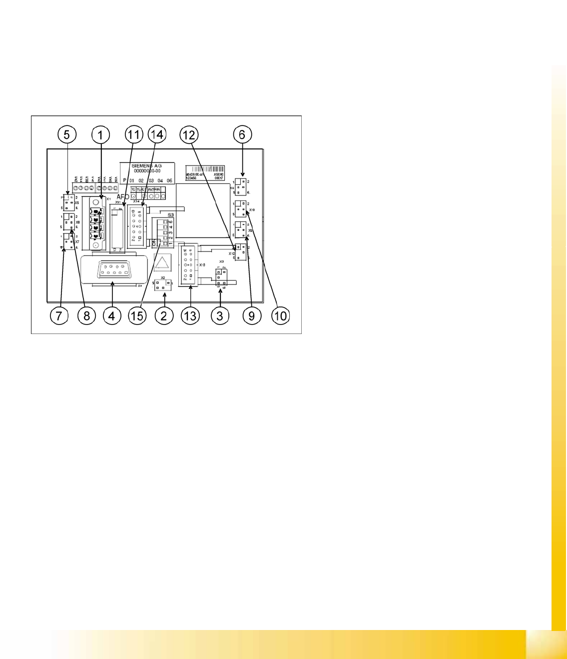
CAN node NC tape cutter module
1. X1 – Energy supply with automatic CAN ID
2. X2 – Energy supply, tape cutter +24 V/+5 V
3. X3 – Reject bin (nozzles, components)
4. X4 – CAN bus connection
5. X5 – Energy supply to valve (left)
6. X6 – Energy supply to valve (right)
7. X7 – Proximity switch for stroke cylinder in
(left)
8. X8 – Proximity switch for stroke cylinder out
(left)
9. X9 – Proximity switch for stroke cylinder in
(right)
10. X10 – Proximity switch for stroke cylinder out
(right)
11. X11– Test connector, tape cutter
12. X12 – Compressed air valve (additional
pneumatic unit for rejecting components)
13. X13 – Nozzle changer, row 1
14. X14 – Nozzle changer, row 2
15. DIP switch group S3
Communication and Control
CAN Bus Tape Cutter and Nozzle Changer - Communication
Student Guide (FSE) SIPLACE X Series and X4I
Communication and Control Edition 01/2009 EN
128
LEDs - meanings
Cable assignment at connector X1
The power connection has 2 pins for selection of the suitable CAN ID. This depends on the position
(location) of the CAN node module in the machine.
DIP switch 3
1 ON: CAN ID DIP switch 2/3 – OFF: Cable select
2CAN -ID 0ON: Gantry 1
ON
OFF.Gantry 2
ON
ON: Gantry 3
OFF
OFF: Gantry 4
OFF: Cable select
3 CAN - ID 1
4 ON: Tape cutter only – OFF: Nozzle changer & tape cutter
5 ON: Module in reset mode – OFF: Module in standard mode
LED Meaning
V39 Component reject bin
V45 Nozzle reject bin
V41 CPU green status LED
V43 CPU red status LED
V40 Nozzle changer 2 light barrier 24 V
V38 Nozzle changer 2 valve active
V44 Nozzle changer 1 light barrier 24 V
V42 Nozzle changer 1 valve active
Pin Signal name Signal type Comments
1 P_24V Input 24 V energy supply
2 GND - Ground
3 CANID_0 Digital input Ground (open) or 24 V (250 µA) for CAN ID
4 CANID_1 Digital input Ground (open) or 24 V (250 µA) for CAN ID
NOTE:
The old nozzle changer of the C&P20 head can not be used together with the CAN node NC
tape cutter module.
The nozzle changer with new control board can also be used in machines without the CAN
nodes.
Communication and Control
Position Measuring System Axis Control
Student Guide (FSE) SIPLACE X Series and X4I
Edition 01/2009 EN Communication and Control
129
4.4 Axis Control
4.4.1 Position Measuring System
4.4.1.1 Track Signals and Axis Zero Pulse Signal
Our Axes systems consists of the following parts.
Axis controller for main board
Servo amplifier
Motor
Position measuring system with Incremental- scale and -encoder
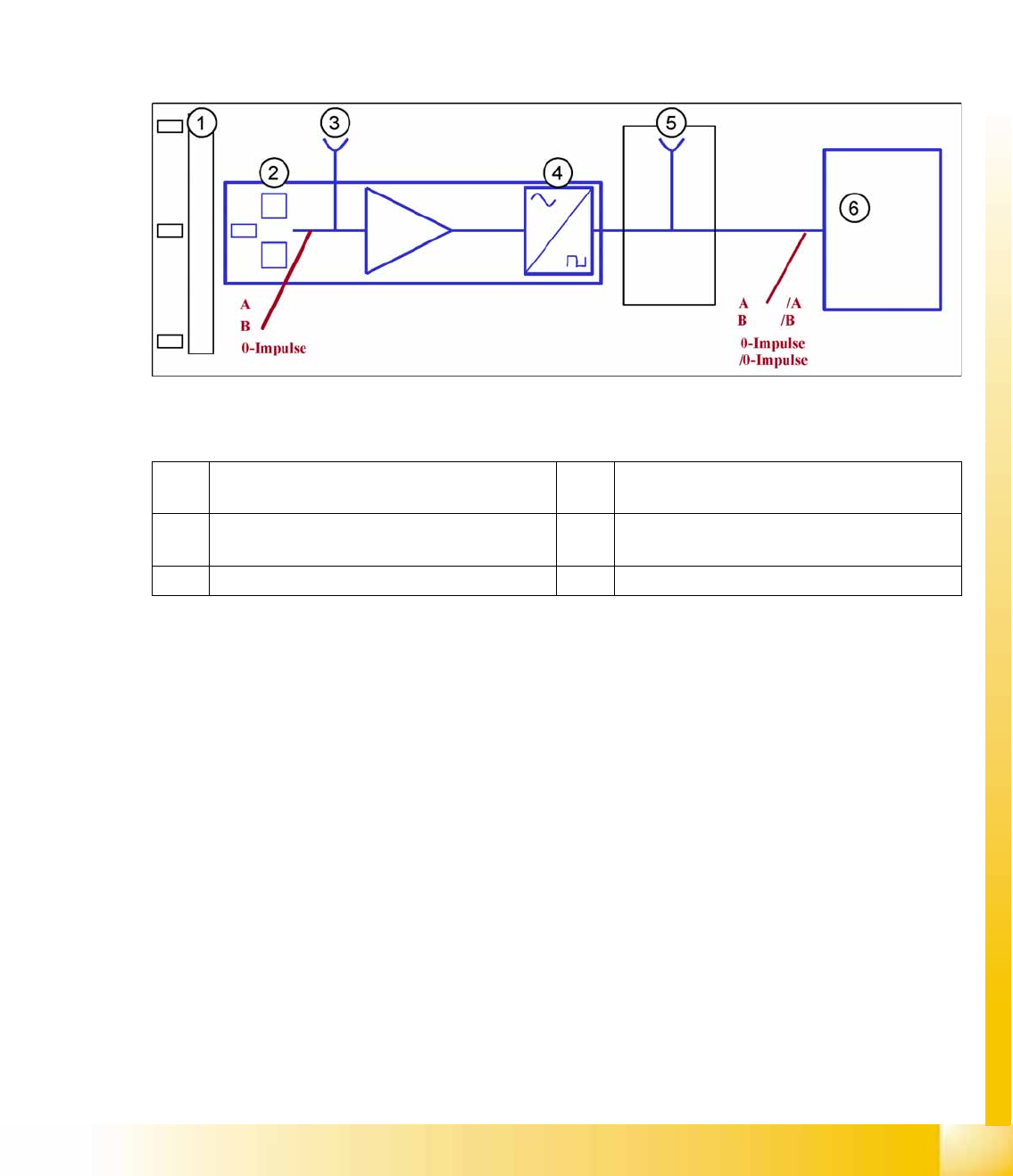
4-30: Principle circuit for position measuring systems
Legend
The axis control system with closed position control circuit determines the axis position directly,
based on the mechanical movement of the axis. The position measurement system generates analog
track and zero pulse signals during movement over the incremental scale. An amplifier, a frequency
multiplier circuit and a signal former are integrated into the amplifier housing. A test connector for digital
signals is either installed on the next interface board or the digital signals are measured at track A/B and
the zero pulse output of the SIPLACE AxisTester. The track signals are the only feedback loops in all
the axis control systems of the SIPLACE machine. This means that each track recognition error affects
the axis control system. The gantry axes immediately stop at a fault; the head axes finish the positioning
to target before showing a track signal error.
The position is determined by a position counter on the axis controller. The direction of axis movement
is determined by the phase shift of the two track signals An advanced track A signal indicates movement
to the right, while an advanced track B signal indicates movement to the left. To make the encoder
system robust for the high resolution we multiply the frequency of the analog signal and create a high
resolution digital measuring system.
1 Incremental scale with zero pulses 4 Electronic signal multiplication and signal
digitalization
2 Incremental encoder for track A / B and
Zeropulse signals (O-pulse.)
5 Test output digital signals
3 Analog signal output and amplifier 6 Axis controller