00196044-05 - sg x und x4i fse_en.pdf - 第365页
Twin Head Description of Boards on the Twin Head Settings S tudent Guide (FSE) SIPL ACE X Series and X4I Edition 01/2009 EN T win Head 365 9.4.1.3 Vision Control Board for IC Camera or FC Camera The vision control board …
Twin Head
Settings Description of Boards on the Twin Head
Student Guide (FSE) SIPLACE X Series and X4I
Twin Head Edition 01/2009 EN
364
To (2) LEDs (description sequence downwards):
LED Color Description
D8 Green Off – return unit is moved out – LED shines briefly
D7 KLEMM Green On - display showing that the return cylinder has been projected downwards.
D6 BERO Green Off - without function (previously: proximity switch Z axis up)
D1 DRUCK Yellow Off - without function (Z pressure)
D2 KLEMM Yellow On – clamping Z axis
Off – return unit is at top position
V2/V_SP Green Shows the voltage supply 15 V for the D-axis track signals.
Off – at jumper setting ON and old force measurement board.
On – Twin Heads with new force measurement board have the 15V regulated on
the main board i.e. the jumper must be set to OFF and the LED will be on.
V3 15V_ Green On – 15 V for the D-axis track signals
V1 TEMP Green On - Z axis motor temperature is OK
D14 ALARM Red Off – alarm output for vacuum generator
On – vacuum generator defect
D9 DRUCK Green Off - without function (Z pressure)
D10 24V+ Green On – 24 V for vacuum generator is OK
Twin Head
Description of Boards on the Twin Head Settings
Student Guide (FSE) SIPLACE X Series and X4I
Edition 01/2009 EN Twin Head
365
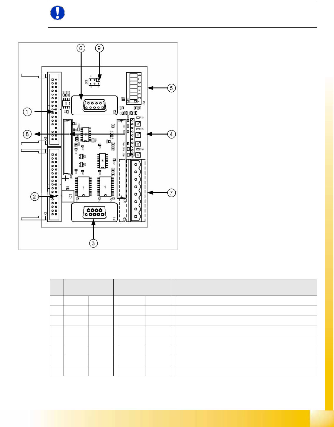
9.4.1.3 Vision Control Board for IC Camera or FC Camera
The vision control board is installed in sector 2 and sector 4 for the stationary cameras.
to 5) DIP switch
NOTE:
When using stationary camera ≧ version 04, the Vision control board is integrated into the
cameras. The Vision control board no longer applies in the sectors.
9-12: Vision control board IC camera
Legend
1. Connector for FC camera illumination
2. Connector for stationary IC camera
illumination
3. Service connector
4. LEDs (downwards D4 - D1)
+5 V/-15 V/+15 V/+40 V
5. DIP switch
6. Connector CAN Bus
7. Voltage supply for Vision control
Connector for DC/DC converter (sector 2)
DC/DC distributor (sector 4)
8. Connectors for 16 bit CAN Bus processor
(TQM modules)
9. Flash signal (not used for Siplace Vision)
S Sector 2
Main distributor
Sector 4
Subdistributor
Description
1OFF OFF CAN terminal resistor - 120 Ohm not set
2OFF OFF RESET
3OFF OFF Bootstrap
4OFF OFF TEST
5OFF ON P1 address switch, gantry ID 1
6ON ONP0 address switch, gantry ID 2
7OFF OFF CAN - ID 1
8OFF OFF CAN -ID 0
Twin Head
Settings Parameter and Calibrations
Student Guide (FSE) SIPLACE X Series and X4I
Twin Head Edition 01/2009 EN
366
9.4.2 Parameter and Calibrations
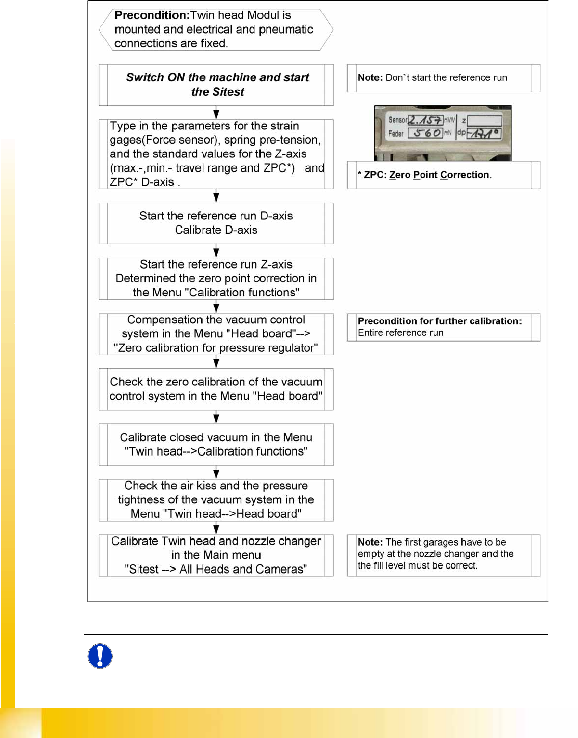
9.4.2.1 Overview of Calibration Steps and Parameters in SITEST
9-13: Overview calibration steps and parameter
NOTE:
This steps are necessary during initial setup or a replacement of the module. The detail
description are explained on the following pages.