00196044-05 - sg x und x4i fse_en.pdf - 第304页
Collect, Pick and Place Head (CPP) Overview Overvi ew of Parts S tudent Guide (FSE) SI PL ACE X Series and X4I Collect, Pick and Place Head (CPP) Edition 01/2 009 EN 304 Pressure Control V alve - Function 8.2.7.3 Z axis …
Collect, Pick and Place Head (CPP)
Overview of Parts Overview
Student Guide (FSE) SIPLACE X Series and X4I
Edition 01/2009 EN Collect, Pick and Place Head (CPP)
303
8.2.7 Overview of Parts
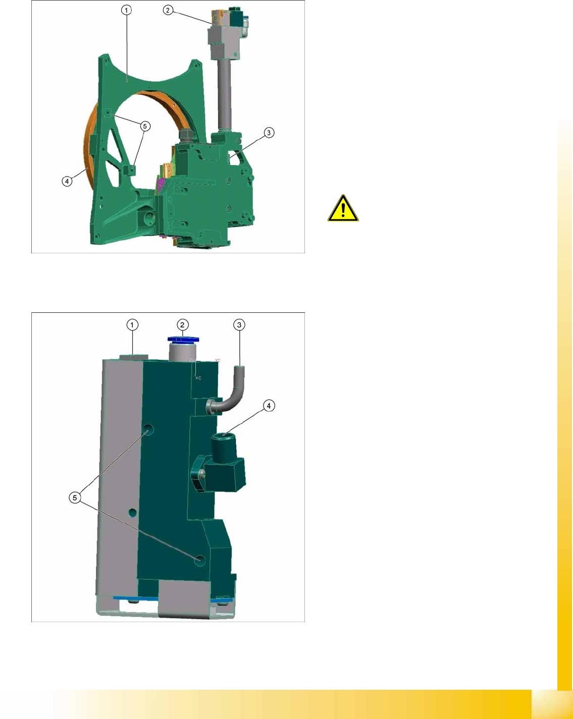
8.2.7.1 Front plate
8.2.7.2 Pressure control valve (digital)
Legend
1. Front plate
2. Return cylinder
3. Z axis with jaws and measuring system
4. Raceway
5. Fixture for pressure control valve
Front plate
The front plate of the CPP head is fixed to the head
housing with four screws and needs to be
removed as a whole unit for service purposes.
ATTENTION:
Do not dismantle any of the
attachments from the front plate, as all
attachments are coordinated with one
another and require special settings.
Legend
1. Energy and data supply
2. Compressed air connection
3. Vacuum/air blast output for pickup/placement
circuit
4. Discharged air, for cooling the X motor
5. Fixture for fastening the pressure control valve
to the front plate
The pressure control valve supplies the
pickup/placement circuit with vacuum during
the pickup process and switches over to air
blast during placement.
The digital pressure control valve can be
adjusted infinitely between max. vacuum and
max. air blast in the pickup/place circuit.
The complete press control valve can be
replaced during service work.
Collect, Pick and Place Head (CPP)
Overview Overview of Parts
Student Guide (FSE) SIPLACE X Series and X4I
Collect, Pick and Place Head (CPP) Edition 01/2009 EN
304
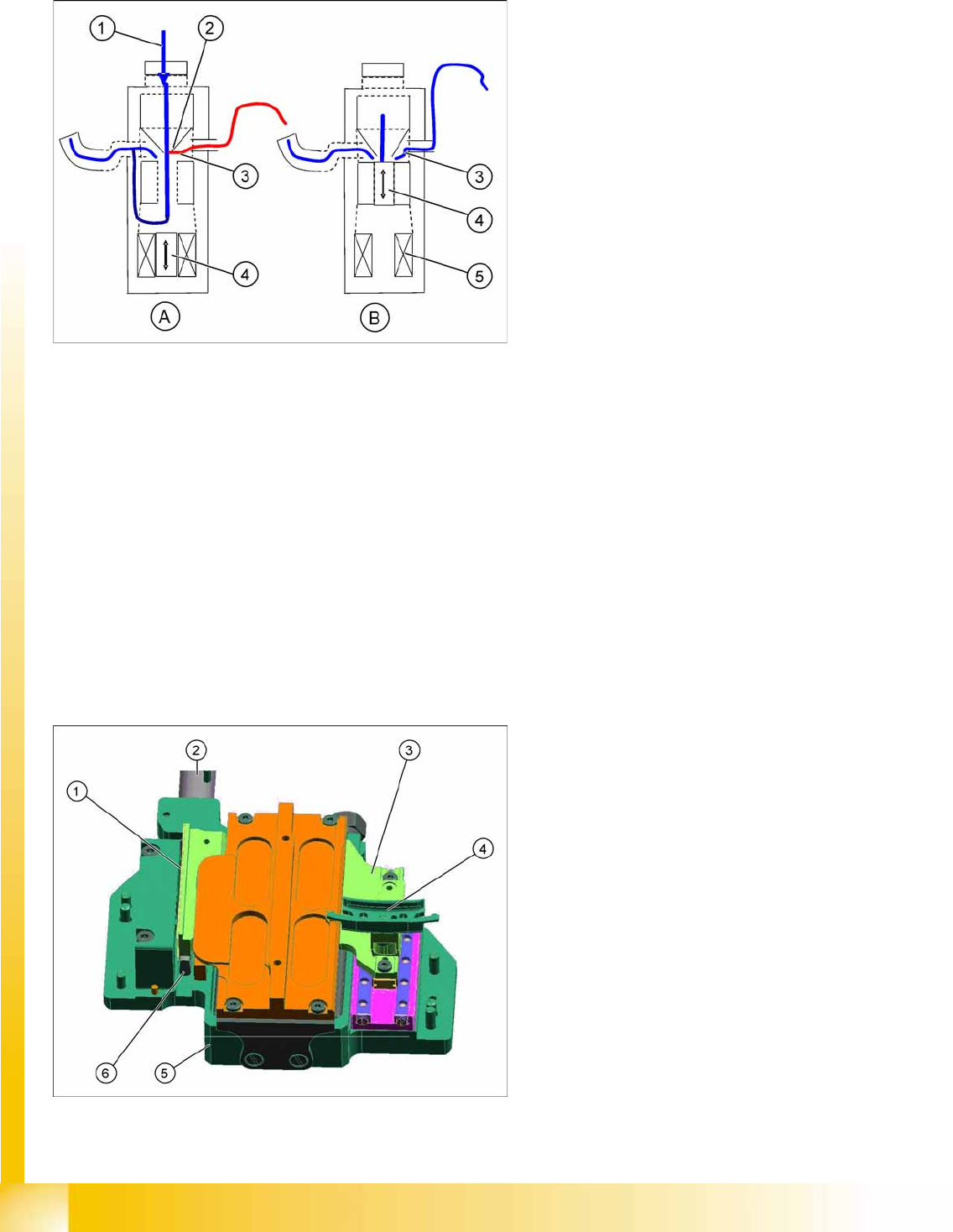
Pressure Control Valve - Function
8.2.7.3 Z axis
Legend
A : Piston setting for max. vacuum during pickup
B : Piston setting for air blast during placement
1. Compressed air inlet
2. Venturi nozzle
3. Vacuum or air blast outlet, depending on
piston setting
4. Pistons
5. Motor
After initialization, the piston is in a central
position, in which neither vacuum nor air blast
is applied to the nozzle.
During pickup, the piston is always in the
Open
position, so that maximum vacuum is
generated and is present at the nozzle. The
switchover time (pressure build up time)
between max. vacuum of –850 mbar to max.
air blast of +200 mbar ≤ 12ms.
The function
Early vacuum
should always be
switched on for the CPP head.
This ensures that max. vacuum is always
present at the nozzle and that the switchover
to air blast only occurs on placement.
Legend
1. Incremental measurement system, resolution
0.5 µm
2. Return unit
3. Secondary part with magnets
The secondary part is fitted to the Z axis.
4. Jaws
The jaws are fitted to the linear guidance of the
Z axis.
5. Linear motor, primary part
6. Actuator on the return unit
Collect, Pick and Place Head (CPP)
Overview of Parts Overview
Student Guide (FSE) SIPLACE X Series and X4I
Edition 01/2009 EN Collect, Pick and Place Head (CPP)
305
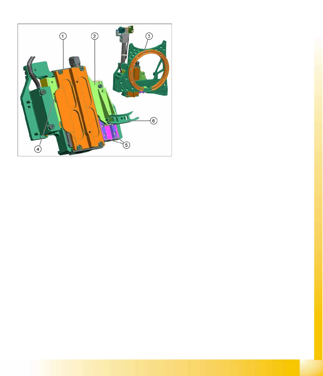
The secondary part with the magnets is part of the Y axis and the primary part is fixed. Benefit, there
are no moveable cables for supplying power to the motor.
The jaws are installed on the secondary part of the Z motor, for mechanical docking of the DP drives.
This return unit keeps the Z axis in the safe, upper position during zero current.
The Z drive forms a complete unit, together with the head front plate, jaws, raceway, measuring
system and return unit. Do not remove or replace individual parts of this unit, as precise settings are
required for each part.
Z Drive Function
The Z drive is a 3 phase linear motor. The moveable part (magnets) is guided on the one side via
two linear guidances and, on the other side, through a support roller.
The incremental measuring system is located on the side with the support roller.
Each Z drive has an EEPROM, in which the following data is stored:
– Production data (manufacturer, serial number, ...)
– Operating data (errors, travel cycles, ...)
– Machine data (motor data, travel profiles, zero point correction, max. and min. position)
The measuring system has a resolution of 0.5 µm. The zero pulse is approx. 2 mm under the top
stop.
New servo amplifier for A364 SDS120/1.5Z2
Legend
1. Z motor, primary part
2. Z motor, secondary part
3. Raceway
4. Support roller
5. Linear guidance Z axis
6. Snap jaws