00196044-05 - sg x und x4i fse_en.pdf - 第85页
Overview CPP Head Overview of Components S tudent Guide (FSE) SIPL ACE X Series and X4I Edition 01/2009 EN Overview 85 3.2.1 1.4 Nozzle Changer (NC) 3-30: Nozzle changer for X machine Legend In X series machines, a max…

Overview
Overview of Components CPP Head
Student Guide (FSE) SIPLACE X Series and X4I
Overview Edition 01/2009 EN
84
3.2.11.3 Description
The CPP head can be operated in various placement modes. The standard mode for the CPP head is
Collect&Place. This is possible up to a component size of 27 mm x 27 mm. The two additional placement
modes, mixed mode for medium/sized components (up to 32 mm x 32 mm) and Pick&Place mode for
large components (up to 50 mm x 40 mm) have significantly increased the component spectrum.
A maximum of twelve components can be picked up from the feeders (X feeders). This value also
depends on the component spectrum.
The component sensor checks the pickup/place positions, to see whether a component has been taken
by the nozzle or placed on a board. On the way to the placement position, the components are rotated
into the correct placement position and optically centered. This is performed with the digital component
camera on the head or, for medium/sized and large components, via a stationary camera. Before
placement is performed, the angle and X/Y position correction, determined by the Vision system, is
applied. The X/Y position correction is calculated into the placement position, while the angle correction
is applied separately to each segment. This is possible as each segment can be rotated independently
of the star position. The components are then carefully and accurately placed down on the board, with
an air blast.
Features:
Each segment has its own DP drive for rotating of the components into the correct position. The
segments are therefore no longer rotated into the correct angle in one single star position but can
now be rotated separately from one another.
Each segment has its own vacuum generator.
The so/called valve terminal is used to switch the supply pressure on and off for each segment. This
reduces the compressed air consumption by up to 40-50%.
In addition, each DP drive has a light barrier Z down. There is no moving cable during the upwards
and downwards movement of the Z axis.
The Z drive for the segments is realized via a linear motor with linear position measuring system.
The secondary part is now integrated into the Y axis, meaning that there is no moving cable during
the upwards and downwards movement of the Z axis.
Overview
CPP Head Overview of Components
Student Guide (FSE) SIPLACE X Series and X4I
Edition 01/2009 EN Overview
85
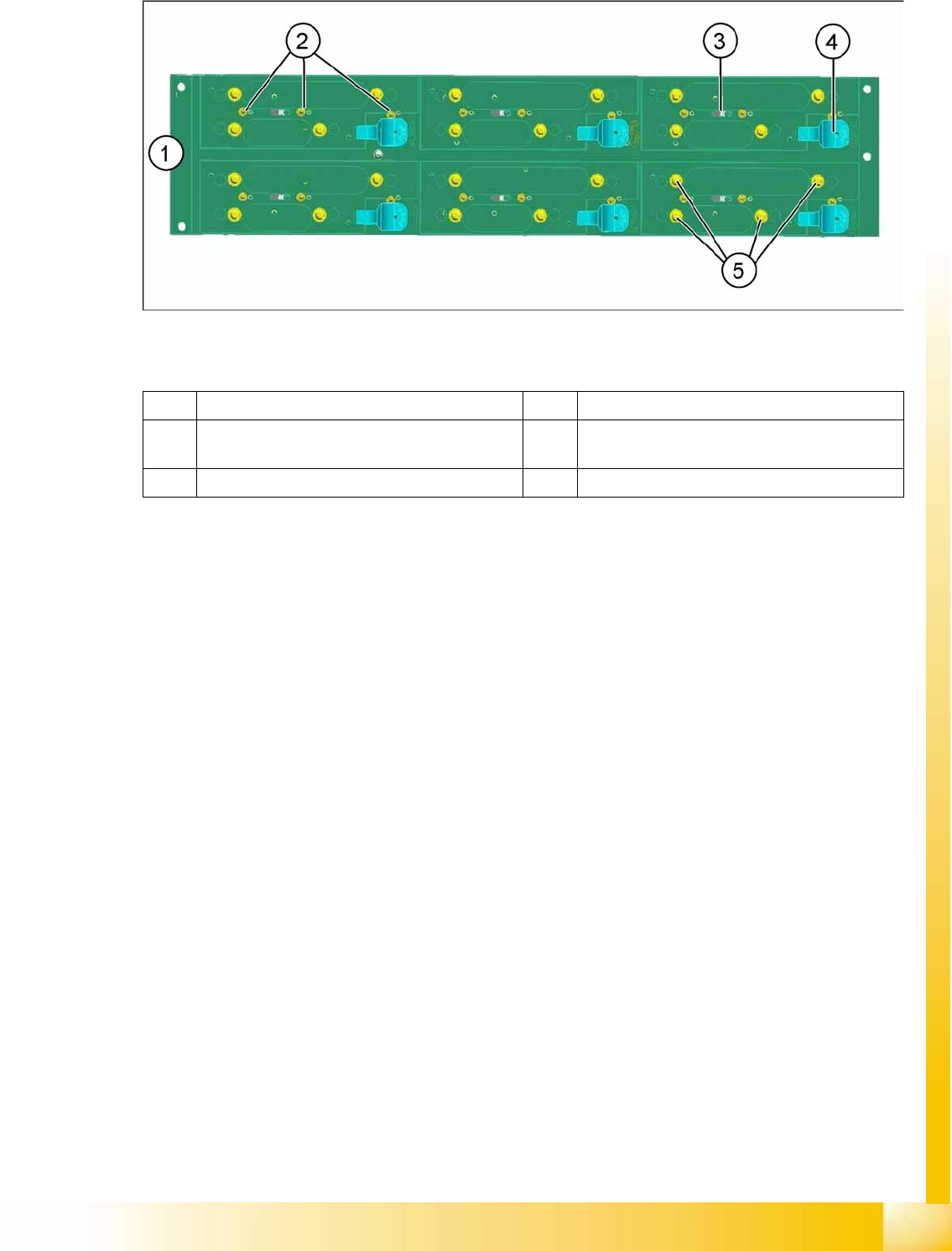
3.2.11.4 Nozzle Changer (NC)
3-30: Nozzle changer for X machine
Legend
In X series machines, a maximum of twelve nozzle changers are possible for each location,
depending on the machine configuration.
The nozzle changer for the X machines has been extended to include the following functions:
– Magazine ID
– Height query
The nozzle changer carrier can accommodate the various magazine types for the C&P20A and CPP
heads.
The machine recognizes the configured magazines via the magazine query (microswitch).
If the wrong magazines are configured for the head, a warning will be issued to prevent a head crash.
– 10xx magazine: Switch 2 (center) pressed
– 20xx magazine: Switches 1 and 3 pressed
– 28xx magazine: Switches 1, 2 and 3 pressed
(1) Nozzle changer carrier (2) Microswitch 1, 2 and 3 for magazine query
(3) Actuator for opening and closing the NC
magazine
(4) Unlocking lever for NC magazine
(5) Fixture clips for NC magazines
Overview
Overview of Components CPP Head
Student Guide (FSE) SIPLACE X Series and X4I
Overview Edition 01/2009 EN
86
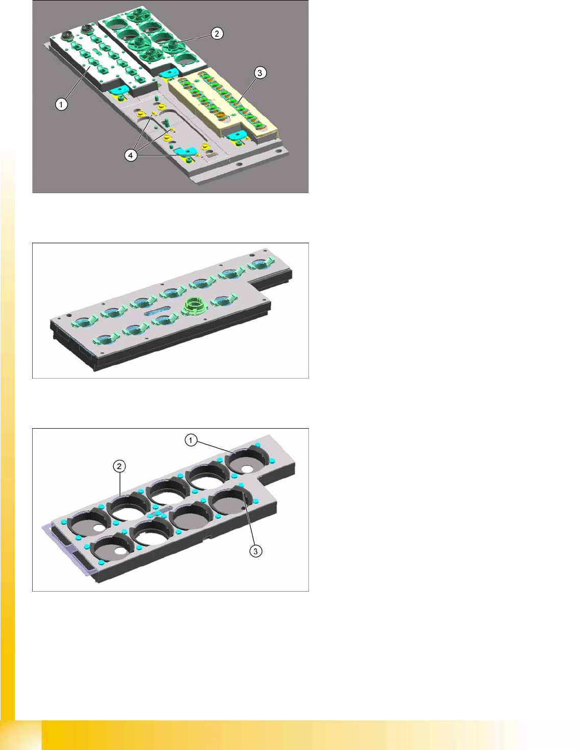
3.2.11.5 Nozzle Magazines
Structure of 20xx Nozzle Magazines
Structure of 28xx Nozzle Magazines
Legend
1. 20xx magazine (CPP)
2. 28xx magazine (CPP)
3. 10xx magazine (C&P20A)
4. Magazine query switch 1, 2 and 3
12 garages per magazine
Antirotation guard for nozzles
Special nozzles up to a max. length of
16.5 mm
Two fiducials per magazine
Legend
1. Five garages for nozzles with a length of up to
12.5 mm (garages 1, 5, 6, 8, 9)
2. Four garages for special nozzles with a length
of up to 16.5 mm (garages 2, 3, 4, 7)
3. Level surface – this is used by special nozzles
for orientation purposes, when they are
nonsymmetrical. The standard 28xx nozzles
are symmetrical.
Antirotation guard for nozzles
Two fiducials per magazine