00196044-05 - sg x und x4i fse_en.pdf - 第430页
Component Handling Pneumatic Tape Cutter Pneumatic Tape Cutter and Empty Tape Duct S tudent Guide (FSE) SI PL ACE X Series and X4I Component Ha ndling Edition 01/2009 EN 430 10.3 Pneumatic T ape Cutter 10.3.1 Pneumatic T…

Component Handling
Error Messages on X Feeder X Feeder
Student Guide (FSE) SIPLACE X Series and X4I
Edition 01/2009 EN Component Handling
429
EEP-WriteErr
(Fehler bei der
Datensicherung
im EEPROM)
Red Data backup has not been
performed correctly in the
EEPROM.
Since the position of the drive is
stored in the EEPROM, a reference
run is necessary in these cases. →
Acknowledge the error with the gray
button. Now confirm request to
perform reference run, with the
yellow button (see Reference Run
for details).
EEP-ReadErr
(Fehler beim
Auslesen des
EEPROMS)
Red Data from the EEPROM have
not been correctly read.
EEP-DataErr
(Fehler beim
Sichern der Daten
im EEPROM)
Red Data backup has not been
performed completely in the
EEPROM.
Reference
Referenz o
Red Tape drive position
information is not available.
Remove the tape. Then perform a
reference run by pressing the yellow
"Foil" button.
CAN BusError
(CAN-Bus-Fehler)
Red CAN Bus Error If pressing reset does not solve the
problem, send the feeder in for
repairs.
ParNotSaved!
Red The parameters were not
saved.
The default parameters are
automatically loaded i.e. the last
operator settings are overwritten →
you may need to change settings
(e.g. cycle). If this error occurs
frequently, replace the control
board.
ParWrongSav
e
Red Parameters were incorrectly
or incompletely saved.
BootFlashErr
FlashDataErr
Red Unable to correctly write data
in boot or application memory.
Replace feeder or control board.
Display LED
display
Meaning Troubleshooting
Component Handling
Pneumatic Tape Cutter Pneumatic Tape Cutter and Empty Tape Duct
Student Guide (FSE) SIPLACE X Series and X4I
Component Handling Edition 01/2009 EN
430
10.3 Pneumatic Tape Cutter
10.3.1 Pneumatic Tape Cutter and Empty Tape Duct
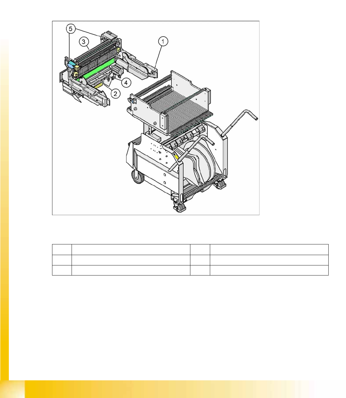
The pneumatic tape cutter unit is fixed to the frame of the docking unit with 4 screws. It separates plastic,
aluminum and paper tapes up to a maximum pocket depth of 25 mm. The tape clippings fall down the
waste slide, into the waste tape bin of the component trolley.
The empty tape duct is constructed so that it covers the cutting edges of the tape cutter (for safety), so
that it controls movement of the empty component tapes to the cutter, so that the component reject bin
is integrated and so that it can receive the various nozzle changers for the C&P6/12/20 and TwinHead.
10-30: Complete docking unit
Legend
1 Frame docking unit 2 Pneumatic Tape Cutter
3 Component reject bin 4 Empty tape duct
5 Support for the nozzle changer
Component Handling
Structure and Function of the Pneumatic Tape Cutter Pneumatic Tape Cutter
Student Guide (FSE) SIPLACE X Series and X4I
Edition 01/2009 EN Component Handling
431
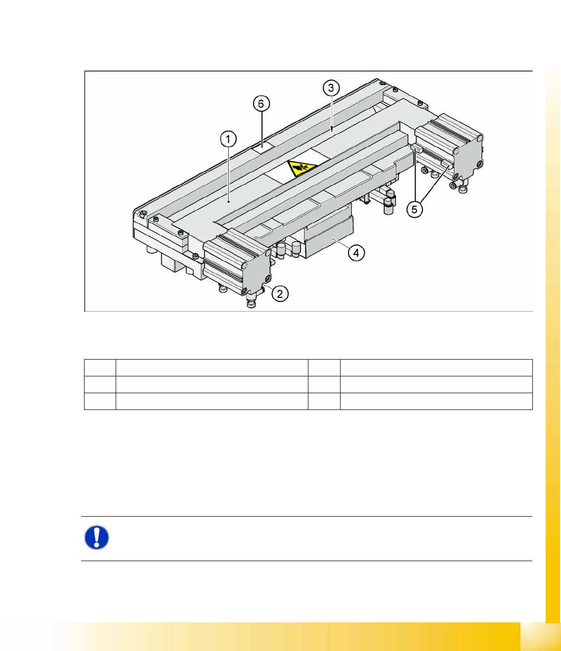
10.3.2 Structure and Function of the Pneumatic Tape Cutter
The empty tape duct guides the empty tapes through the opening (3) in the cutter.
The cutter is based on a horizontal frame (1) with a fixed cutting edge and a flexible blade, which is
moved by two short-stroke cylinders (2). At each upwards or downwards movement, the device cuts off
the tape.
The proximity switch (5) signals the position of the short-stroke cylinder piston and therefore the position
of the cutter blade. The proximity switch enables the control electronics (4) to register whether the tape
has been cut. Cutting only takes place during placement. For operational safety reasons, the tape cutter
is integrated into the emergency stop circuit.
The pneumatic tape cutter is fixed on the frame of the docking unit with four screws and this, together
with the empty tape duct is a complete unit.
10-31: Pneumatic Tape Cutter
Legend
The tape cutter is activated when the gantry moves to the first placement position. Alternating one of the
cylinders start to front position. Once the first cylinder reaches the front position, the second cylinder is
started. Both signals ’blade in front position’ trigger control unit to withdraw both cylinders at the same
time.
The cutter can be removed in about 15 minutes for service purposes. For detailed information about
dismantling, refer to the service manual.
1 Horizontal frame 4 Electronic control unit
2 Pneumatic cylinder 5 Proximity switch
3 Slot for empty tape 6
NOTE:
The spare parts numbers for the cutters and the cutter blades are not identical between HF and
X machines.