00196044-05 - sg x und x4i fse_en.pdf - 第325页
Collect, Pick and Place Head (CPP) Placement Modes Pickup and Placement Cycle for CPP S tudent Guide (FSE) SIPL ACE X Series and X4I Edition 01/2009 EN Collect, Pick and Place Head (CPP) 325 8.4.2.3 Pick&Place Mode M…
Collect, Pick and Place Head (CPP)
Pickup and Placement Cycle for CPP Placement Modes
Student Guide (FSE) SIPLACE X Series and X4I
Collect, Pick and Place Head (CPP) Edition 01/2009 EN
324
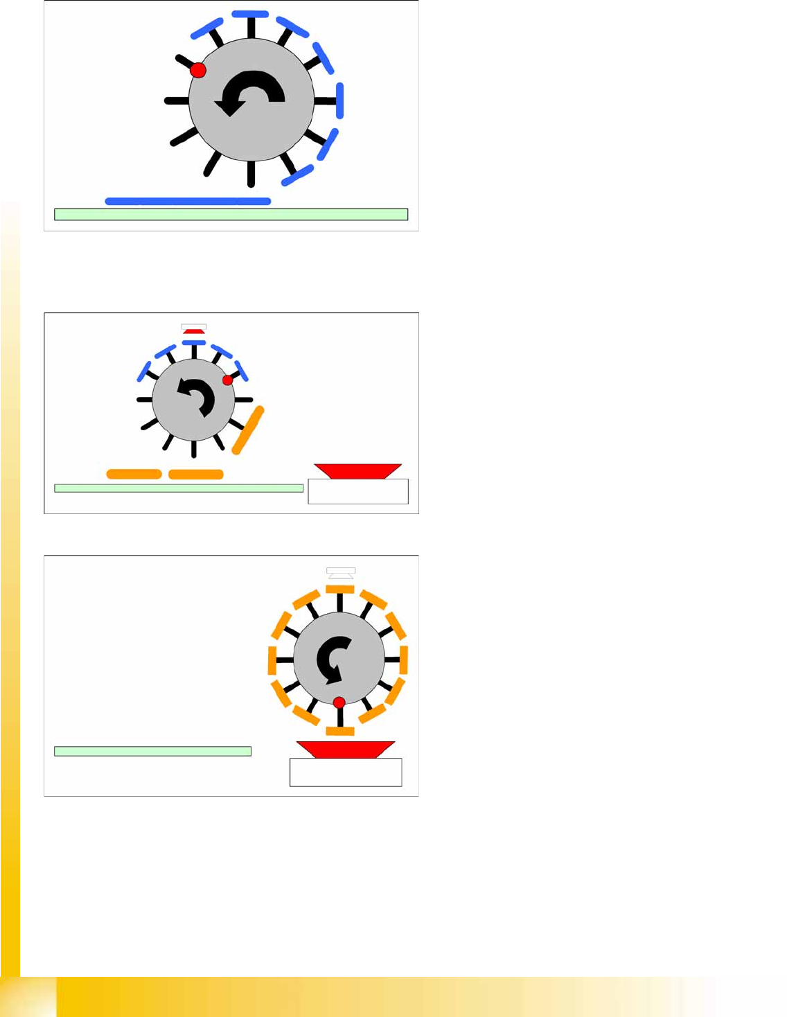
8.4.2.1 Collect&Place Mode
8.4.2.2 Mixed Mode
Component spectrum:
01005 to 27x27 mm
8.5 mm high
Speed:
20,000 to 24,000 CO/h
Accuracy:
+/- 50 µm (4 sigma)
0.3° (4 sigma)
Mixed mode 1
Component spectrum:
01005 to 32x32 mm
11.5 mm height
Accuracy:
+/- 45 μm (4 sigma) with stationary camera
Mixed mode 2
Component spectrum: 01005-32x32mm,
11.5 mm height
Accuracy:
+/- 45 μm (4 sigma) with stationary camera
Collect, Pick and Place Head (CPP)
Placement Modes Pickup and Placement Cycle for CPP
Student Guide (FSE) SIPLACE X Series and X4I
Edition 01/2009 EN Collect, Pick and Place Head (CPP)
325
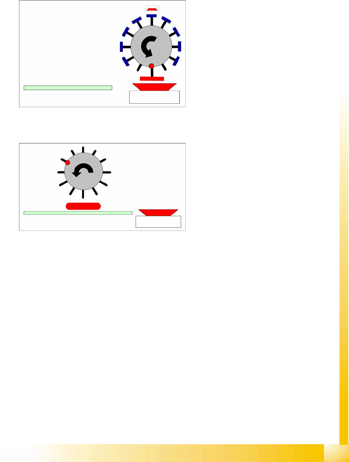
8.4.2.3 Pick&Place Mode
Mixed mode 3
Component spectrum:
01005 to 32x32 mm,
11.5 mm height
Accuracy:
+/- 45 μm (4 sigma) with stationary camera
Component spectrum:
01005 to 50x40 mm
11.5 mm height
Speed:
Up to 1.500 cph
Accuracy:
+/- 40 µm (4 sigma)
0.1° (4 sigma)
Collect, Pick and Place Head (CPP)
Pickup and Placement Cycle for CPP Board Position Recognition
Student Guide (FSE) SIPLACE X Series and X4I
Collect, Pick and Place Head (CPP) Edition 01/2009 EN
326
8.4.3 Board Position Recognition
We differentiate between standard position recognition and dual position recognition.
PCB – position recognition (standard position recognition)
Board position recognition is used to determine the exact position of the board in the machine (conveyor
--> placement area).
PCB position recognition is performed with gantry 4 for placement area 1 and with gantry 2 in placement
area 2.
There should be at least two fiducials on each PCB. These are then used to calculated the X/Y position
and the rotary angle of the board, in the conveyor system.
The fiducials should not be on the same line as one another.
Up to 3 fiducials can be programmed for position recognition. With the third fiducial you can also
determine and correct any displacement within the board (shrinkage, stretched).
Dual position recognition (for alternating mode only)
Dual position recognition is required in order to guarantee the placement accuracy. Materials change
according to the temperature they are subjected to and the same applies to the machine gantries.
Dual position recognition is performed with gantry 1 in placement area 1 and with gantry 3 in placement
area 2.
In the case of dual position recognition, gantry 1/3 uses the fiducial position recognition values from
gantry 2/4 to calculate the placement offset for gantry 1/3. Depending on the arrangement of fiducials on
the board, either 2 or 3 fiducials will be used for dual position recognition.
The fiducials for dual position recognition are selected so that the calculation performed can be as
accurate as possible.
Temperature compensation
A further measure to ensure placement accuracy is the temperature compensation with the help of
sensors on the head plate. The head plate features two temperature sensors, the temperature values of
which are regularly checked via a separate bus system.
The software uses these temperature values to calculate an offset value, which is added to the head
offset.
Head offset SW 60x is the distance PCB <--> component camera
Head offset SW 70x is the distance PCB camera <--> nozzle tip
The temperature reference value is the temperature during the last machine calibration.
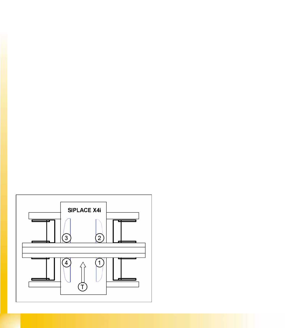
SIPLACE X4I:
Gantry 4 – position recognition with max. 3
fiducials
Gantry 2 – position recognition with 2 fiducials
Gantries 1 and 3 – dual position recognition
Legend
1: Gantry 1
2: Gantry 2
3: Gantry 3
4: Gantry 4
T: Transport direction