00196044-05 - sg x und x4i fse_en.pdf - 第448页
Modular Conveyor Techni cal Data Technical data - single conveyor S tudent Guide (FSE) SI PL ACE X Series and X4I Modular Conveyor Edition 01/2009 EN 448 1 1.1.14.5 Overview of Quad Lane Conveyor See also: J 11.3.2 Setti…
Modular Conveyor
Conveyor Modes Function Description
Student Guide (FSE) SIPLACE X Series and X4I
Edition 01/2009 EN Modular Conveyor
447
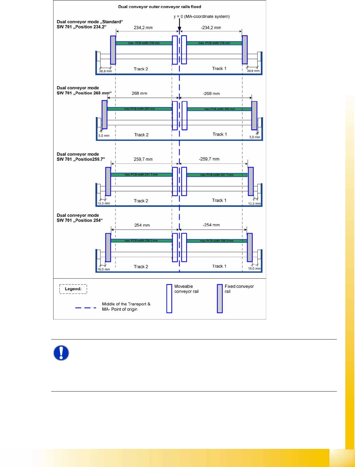
11.1.14.4 Overview of Dual Conveyor I-Placement
11-6: Dual conveyor i-placement
See also:
J
11.3.2 Setting the Fixed Conveyor Side (from SW701) [
J
452]
NOTE:
During service work, the distance between the fixed side and the shaft fixtures is set to 38.8 with
the gauge, in standard mode. The other dimensions are calculated automatically by the
software.
The term
Position 'xxx.x'
in the diagram refers to the buttons in the station software, for setting
the fixed conveyor side.
Modular Conveyor
Technical Data Technical data - single conveyor
Student Guide (FSE) SIPLACE X Series and X4I
Modular Conveyor Edition 01/2009 EN
448
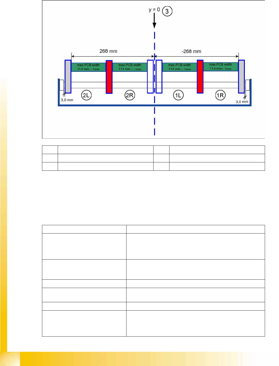
11.1.14.5 Overview of Quad Lane Conveyor
See also:
J
11.3.2 Setting the Fixed Conveyor Side (from SW701) [
J
452]
11.2 Technical Data
11.2.1 Technical data - single conveyor
(1L) Lane 1 left (2L) Lane 2 left
(1R) Lane 1 right (2R) Lane 2 right
(3) Machine coordinate system
Fixed conveyor side Right (standard), left (optional)
Max. component height 6 mm for the C&P12
8.5 mm for the C&P6
4 mm for the C&P20A
25 mm for the Twin Head
PCB format (LxW) 50 mm x 50 mm to 450 mm x 508 mm
2" x 2" to 18" x 20"
long board to 610 mm (24"), (option)
PCB thickness 0.3 mm to 4.5 mm
Max. PCB warpage upwards: 6 mm - board thickness
Downwards: 0.3 mm + PCB thickness
Clearance on PCB underside max. 40 mm
PCB transport height 830 mm ±15 mm (standard)
900 mm ±15 mm (option)
930 mm±15 mm (option)
950 mm ±15 mm (option SMEMA)
Modular Conveyor
Technical data - dual conveyor Technical Data
Student Guide (FSE) SIPLACE X Series and X4I
Edition 01/2009 EN Modular Conveyor
449
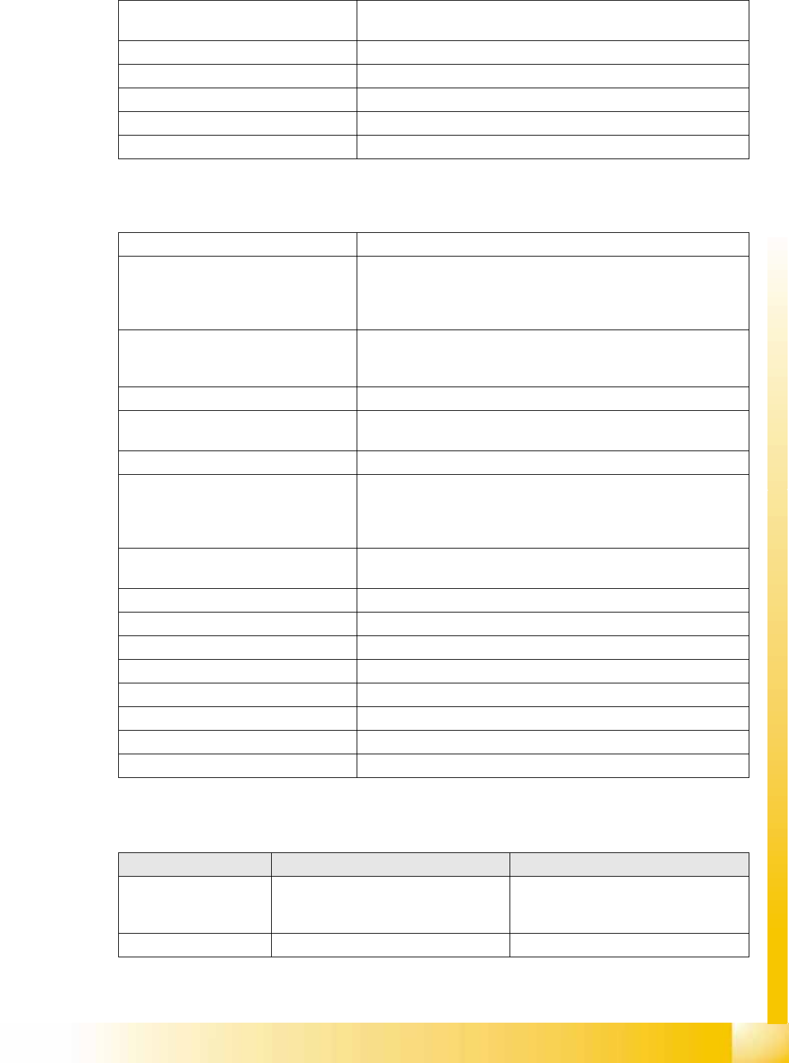
11.2.2 Technical data - dual conveyor
11.2.3 Technical data - flexible dual conveyor
Type of interface SMEMA (standard)
SIEMENS (option)
PCB weight 3 kg
Component-free handling edge 3 mm
PCB changeover time 2.5 s
Ink spot recognition possible
Automatic width adjustment possible
Fixed conveyor side Right (standard), left (optional)
Max. component height 6 mm for the C&P12
8.5 mm for the C&P6
4 mm for the C&P20A
25 mm for the Twin Head
PCB format (LxW) 50 mm x 50 mm to 450 mm x 250 mm
2" x 2" to 18" x 8,5"
Long board to 610 mm (24") (option)
PCB thickness 0.3 mm to 4.5 mm
Max. PCB warpage upwards: 6 mm - board thickness
Downwards: 0.3 mm + PCB thickness
Clearance on PCB underside max. 40 mm
PCB transport height 830 mm ± 15 mm (standard)
900 mm ± 15 mm (option)
930 mm± 15 mm (option)
950 mm ± 15 mm (option SMEMA)
Type of interface SMEMA (standard)
SIEMENS (option)
PCB weight 3 kg
Component-free handling edge 3 mm
PCB changeover time 2.5 s
Conveyor mode synchronous or asynchronous
Components on each conveyor same or different
PCB width on each conveyor same or different
Ink spot recognition synchronous: not possible, asynchronous: possible
Automatic width adjustment possible
Feature Single conveyor mode Dual conveyor mode
Max. board size 450 x 450 mm (B x L)
Widths of up to 380 mm are possible in
combination with X3/X2/X4 machines.
250 x 450 mm (B x L)
Widths of up to 450 216 mm are possible
in combination with X3/X2/X4 machines.
Long board option Possible board length: up to 610 mm Possible board length: up to 610 mm