00196044-05 - sg x und x4i fse_en.pdf - 第257页
C&P20A Height Reference Run Reference Run for C&P20A Head S tudent Guide (FSE) SIPL ACE X Series and X4I Edition 01/2009 EN C&P20A 257 7.3.6 Height Reference Run With this function we check the correct fittin…
C&P20A
Reference Run for C&P20A Head Cleaning Cycle - Procedure
Student Guide (FSE) SIPLACE X Series and X4I
C&P20A Edition 01/2009 EN
256
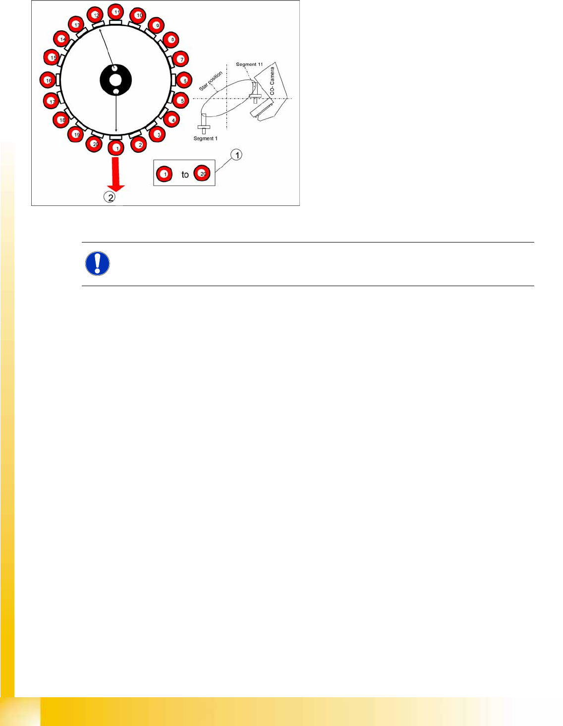
7.3.5 Cleaning Cycle - Procedure
7-13: Vacuum check procedure
The gantry axes move the C&P head to the
reject position so that the nozzles can be
cleaned before the measuring cycle.
The Star axes move in an anticlockwise
direction and all cleaning functions are
performed at the same time, within one head
cycle.
1. The DP drives rotate each segment into the 0°
position.
2. The digital pressure control valve now
activates the air blast for the reject position.
The components still on the nozzle will be
rejected.
NOTE:
In SIPLACE X machines, components are rejected in the pickup/placement position.
C&P20A
Height Reference Run Reference Run for C&P20A Head
Student Guide (FSE) SIPLACE X Series and X4I
Edition 01/2009 EN C&P20A
257
7.3.6 Height Reference Run
With this function we check the correct fitting of the nozzle on the sleeve and that the correct nozzle type
like the programmed one are set to the sleeves. The nozzle length is taken to calculate the pick up and
placement height for the subsequent placements.
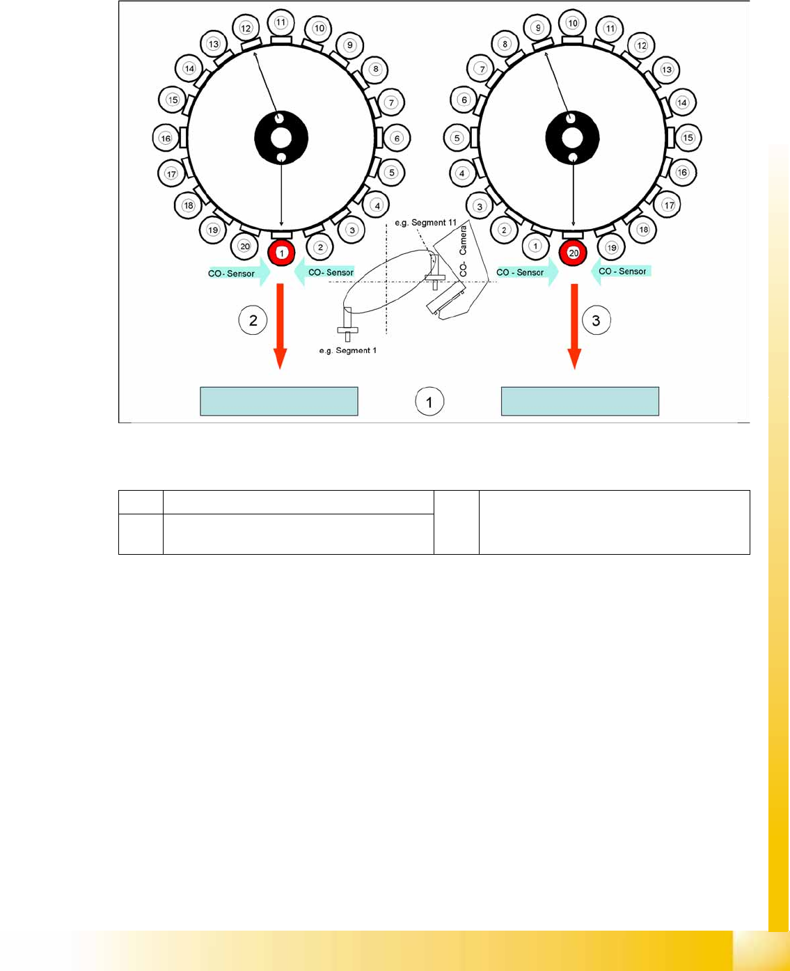
7-14: Measuring the nozzle height
Legend
The gantry moves the placement head to the fixed conveyor side at height measurement position.
The star turns the segment for measuring into the pickup/placement position
The value "Vacuum open" is measured for each segment.
The Z axis is positioned downwards:
When the component sensor beam is interrupted, the Z position of the axis is determined for the
component sensor.
When the Z axis touches the conveyor side, the mechanical nozzle length is determined by the Z
position value and the closed vacuum value is measured.
The Z axis is positioned upwards:
When the component sensor beam is no longer interrupted, the Z position of the axis will be
measured again for the component sensor.
1 Top edge of the fixed conveyor side 3 Last step with segment 20 to measure the
nozzle length.
2 First step with segment 1 to measure the nozzle
length.
C&P20A
Reference Run for C&P20A Head Height Reference Run
Student Guide (FSE) SIPLACE X Series and X4I
C&P20A Edition 01/2009 EN
258
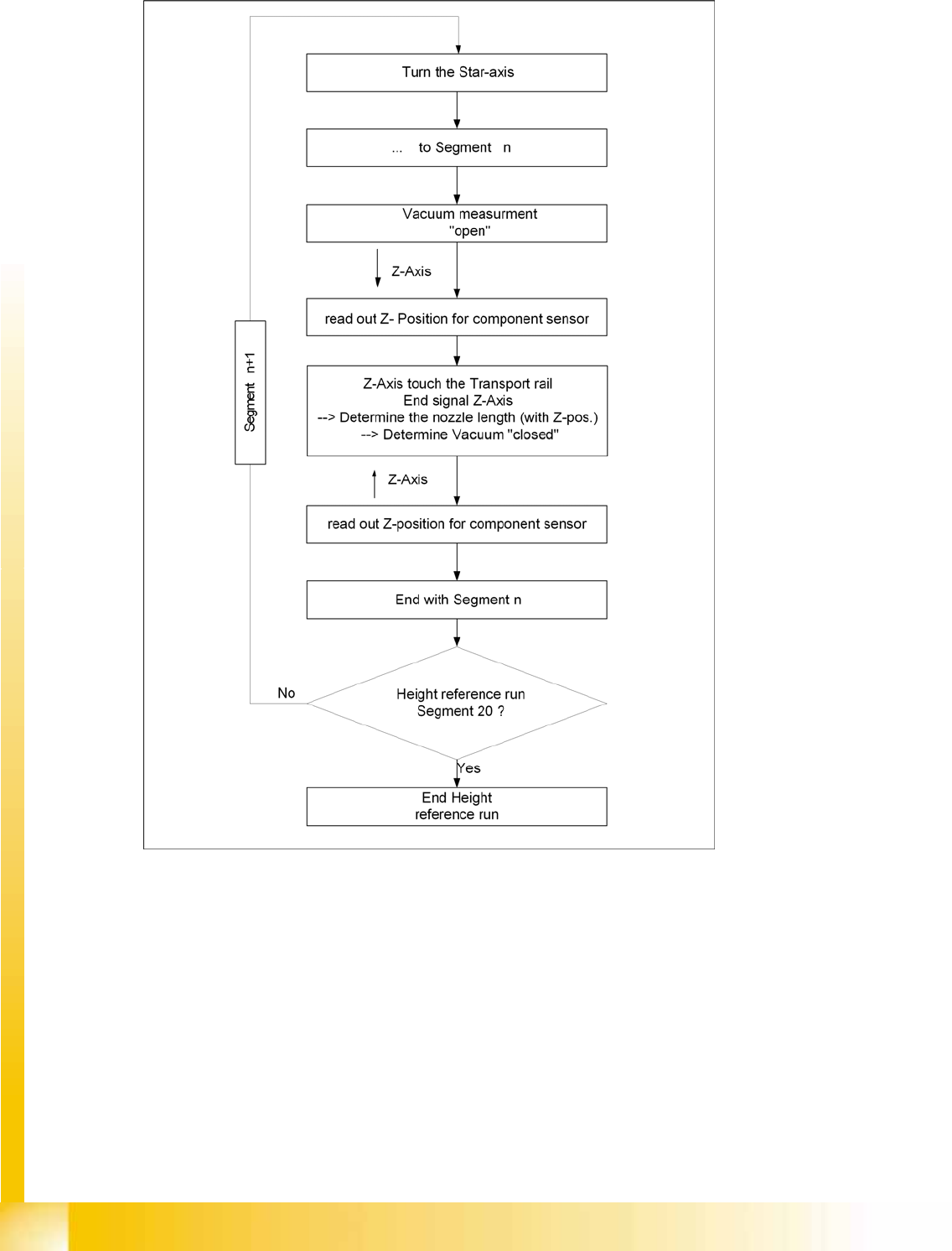
7.3.6.1 Sequence of Height Reference Run
7-15: Height reference run flow chart