00196044-05 - sg x und x4i fse_en.pdf - 第248页
C&P20A Overview Parts Overview with Function Description S tudent Guide (FSE) SI PL ACE X Series and X4I C&P20A Edition 01/2009 EN 248 St ar Drive See also: J 7.2.5.1 Ov erview of Air Bla st Supply [ J 251] J 7…
C&P20A
Parts Overview with Function Description Overview
Student Guide (FSE) SIPLACE X Series and X4I
Edition 01/2009 EN C&P20A
247
Measurement System with Hall Sensors – Function:
The sensor detects the movement of ferromagnetic material (toothed wheel) through changes to the
magnetic flow.
If one element is opposite a ferromagnetic tooth and another opposite a gap, this causes a one-sided
increase in induction.
The difference arising between the two elements alters the polarity once the toothed wheel moves.
This change is evaluated, digitized and used to address or give feedback in closed-loop control.
Due to the mechanical arrangement, there is only one 0° position in each segment.
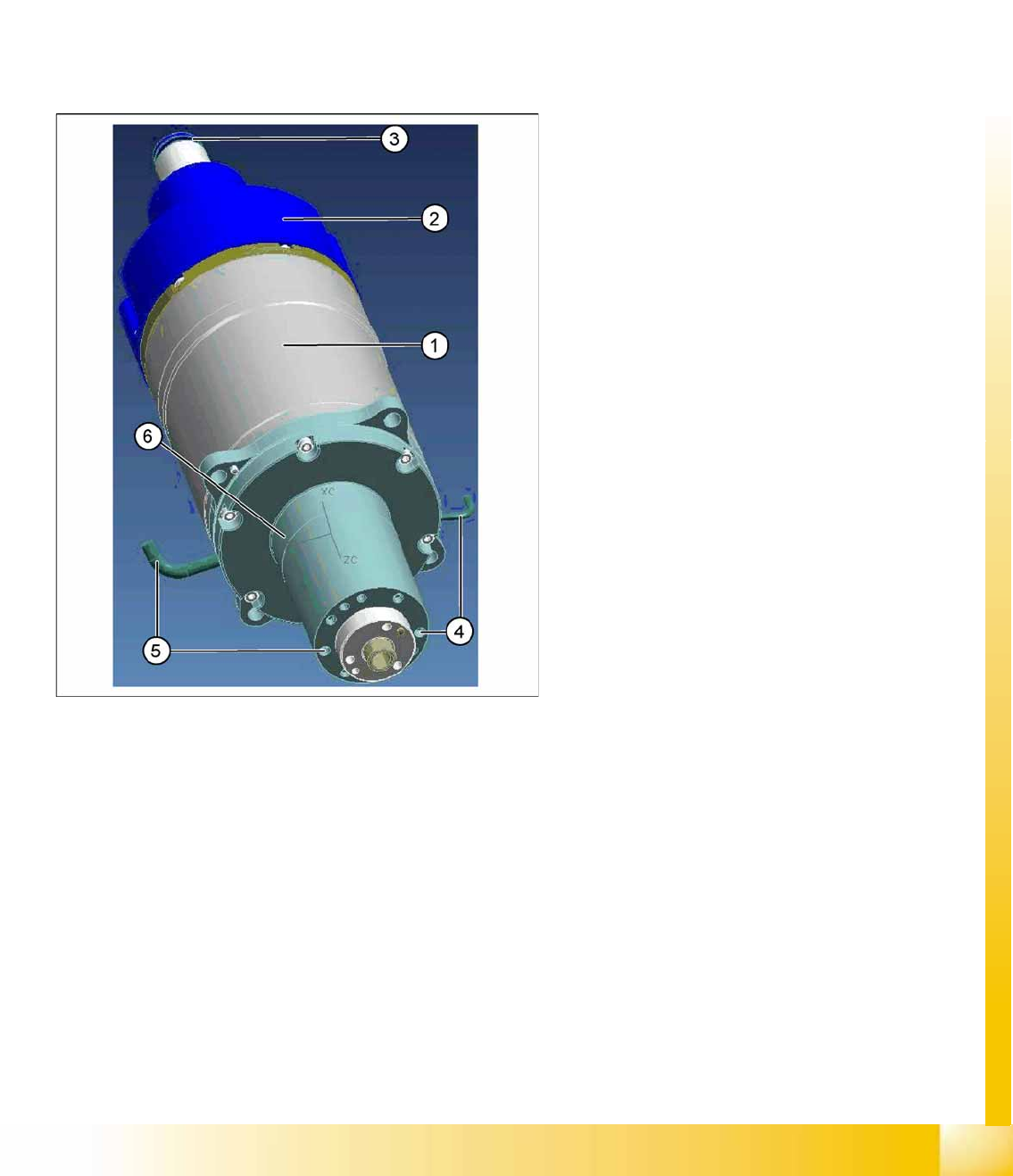
7.2.3.7 Star motor
The star motor has a brushless three-phase drive
with integrated measurement system.
The motor shaft has a hollow design. This enables
compressed air to be supplied to the holding circuit
of the 20 segments.
The vacuum in the holding circuit is measured via
the connection (4).
The air blast and vacuum in the pickup/placement
circuit are measured via the connection (5).
The star motor is not a spare part.
Legend
3-phase alternating current drive (1)
Incremental measurement system (2)
Compressed air connection for hold circuit (3)
Flange on the motor shaft (6).
C&P20A
Overview Parts Overview with Function Description
Student Guide (FSE) SIPLACE X Series and X4I
C&P20A Edition 01/2009 EN
248
Star Drive
See also:
J
7.2.5.1 Overview of Air Blast Supply [
J
251]
J
7.2.5.2 Overview of Vacuum Supply [
J
252]
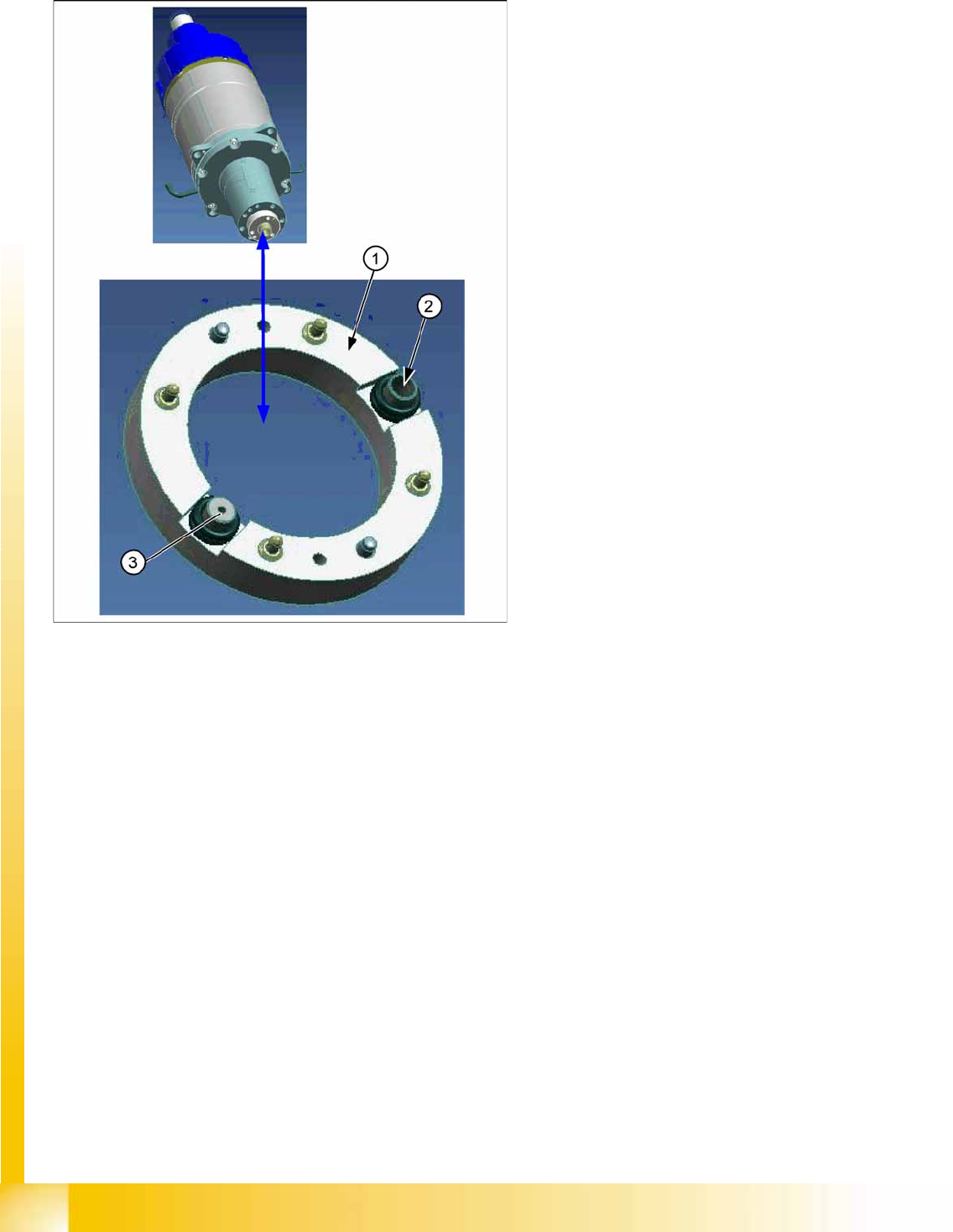
The star motor is a brushless three-phase
drive with sinus commutation.
An optical measurement system is used for
both commutation and recognition of the rotary
angle. This supplies the track signals A, B and
the zero pulse.
The motor is controlled with the help of these
track signals. The actual values of the position
are evaluated on the axis controller. The servo
unit enhances performance and is supplied
with 2-phase current from the axis controller
board. (The third phase is calculated
automatically.)
A flange is installed on the motor shaft. This
flange is screwed to the star carrier. The
smoothed distributor disc (1) is located
between the flange and the star carrier.
The motor shaft has a hole for the compressed
air supply, used to feed the holding circuit.
The smoothed distributor disc enables
vacuum and air blast to be measured in the
hold circuit (3) and placement/pickup circuit
(2).
C&P20A
Parts Overview with Function Description Overview
Student Guide (FSE) SIPLACE X Series and X4I
Edition 01/2009 EN C&P20A
249
7.2.3.8 Component Camera
7.2.3.9 Nozzle changer
Component Camera (Type 23 digital)
The component camera is fixed to the
C&P20A head with 4 screws and can be
replaced during service work.
Five levels are available for illuminating the
components.
Visual field: 8.2 x 8.2 mm
Resolution: 14.1 µm/pixels
Component spectrum 01005-2220 max.
6 x 6 mm, Bare Dies, Flip Chip
Legend
1. Lens system
2. Fixture to head housing
3. Camera amplifier
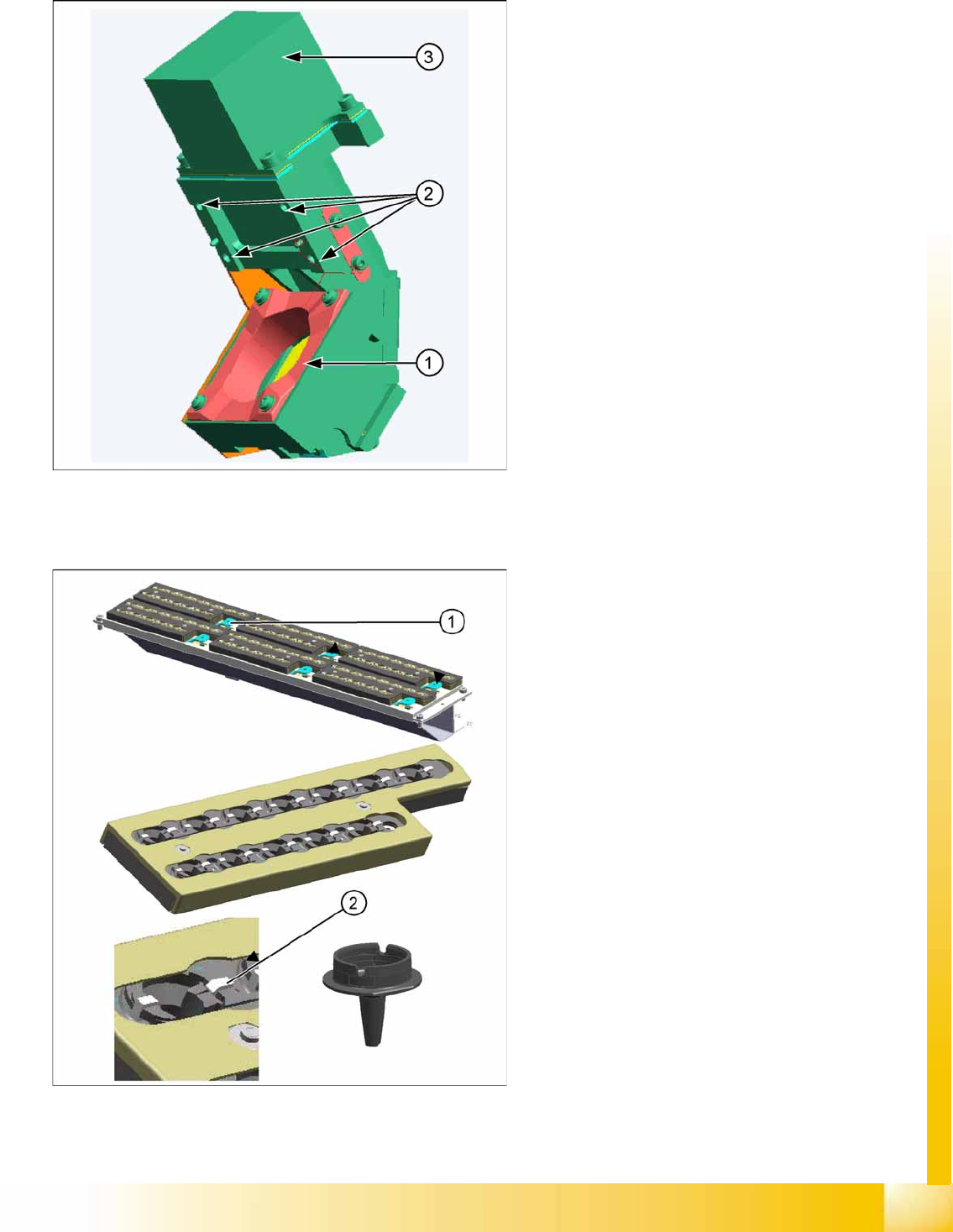
Nozzle Changer (optional)
The nozzle changer has 6 magazines, each
with 12 nozzle garages for individual
configuration.
A maximum of 2 nozzle changers can be
installed per C&P20A head.
(X4I: max. 1 nozzle changer, only 4
magazines at locations 2/4)
If the nozzle changer is backfitted, the height
of the nozzle changer needs to be checked
with a caliper.
Each magazine is recognized via a micro
switch and indicated by a green LED.
Legend
1. Remove magazine
2. Bracket to hold nozzle when placed down