00196044-05 - sg x und x4i fse_en.pdf - 第279页
C&P20A Board Descriptions for C&P20A Settings S tudent Guide (FSE) SIPL ACE X Series and X4I Edition 01/2009 EN C&P20A 279 LEDs - meanings: Test points: Test connector X14: No. Functio n On Off D3 +5 V Presen…
C&P20A
Settings Board Descriptions for C&P20A
Student Guide (FSE) SIPLACE X Series and X4I
C&P20A Edition 01/2009 EN
278
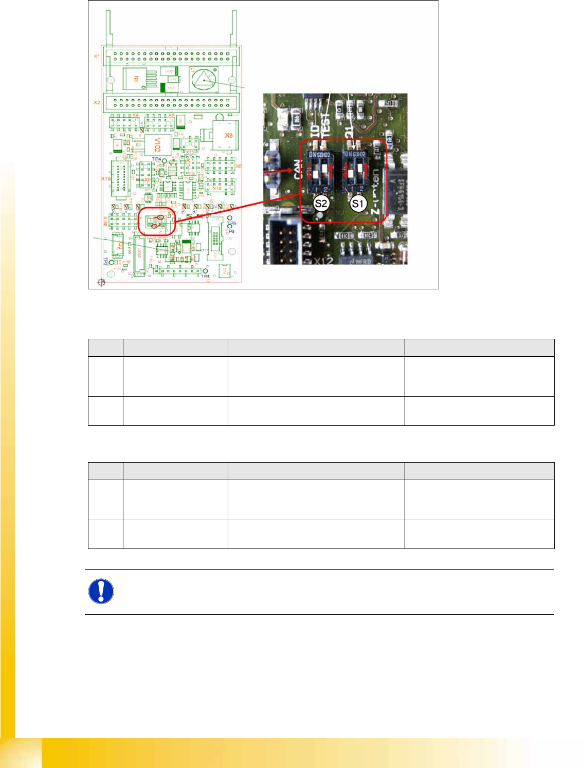
Switch setting S1, S2
7-44: Intermediate distributor - position of DIP switch
S1 (default setting: bold)
S2 (default setting: bold)
No. Function Switch setting = 0 (open) Switch setting = 1 (closed)
S1.1 Z-down sensor: Switch
on LED
LED only switched on during operation LED always on (test mode e.g. for
detection of nozzle suspension with
oscillo.)
S1.2 Z-down sensor: Activate
LED in clocked mode
LED is activated in clocked mode during
operation
LED is always switched on
during operation
No. Function Switch setting = 0 (open) Switch setting = 1 (closed)
S2.1 CAN test Normal operation: 1-wire head CAN
bus only with motherboard - ready for
operation
Test mode: operation without
motherboard possible
S2.2 CAN ID switchover -
pressure control valve
CAN ID active for pressure control valve
0x6B0
CAN ID for pressure control
valve 0x6B8 (test mode)
NOTE:
The default switch setting is always printed in bold.
C&P20A
Board Descriptions for C&P20A Settings
Student Guide (FSE) SIPLACE X Series and X4I
Edition 01/2009 EN C&P20A
279
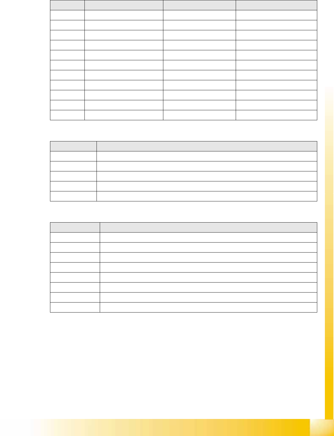
LEDs - meanings:
Test points:
Test connector X14:
No. Function On Off
D3 +5 V Present Not present
D4 Z down Triggered Not triggered
D5 Z down reset Reset Not reset
D6 +15 V Present Not present
D7 +24 V_IN
D8 -15 V Present Not present
V2 Z return valve Activated (down/bottom) Not activated (up/top)
V11 Enable pressure control valve Error - pressure control valve Pressure control valve OK
V14 +24 V Present Not present
V15 +24 V_DP Switched on Switched off
V16/17 Voltage GND
No. Function
TP1 GND
TP3 Voltage pressure signal - pressure control valve - internal
TP4 Output voltage I/U converter Z down
TP5 Z down
TP6 Z up/Z down reset
Pin Signal
1CAN_RX
2GND
3+5 V
4+15 V
5 -15 V
6 X2_11
724V_DP
8 Z up/Z down reset
C&P20A
Settings Overview of Spare Parts and Settings for C&P20A
Student Guide (FSE) SIPLACE X Series and X4I
C&P20A Edition 01/2009 EN
280
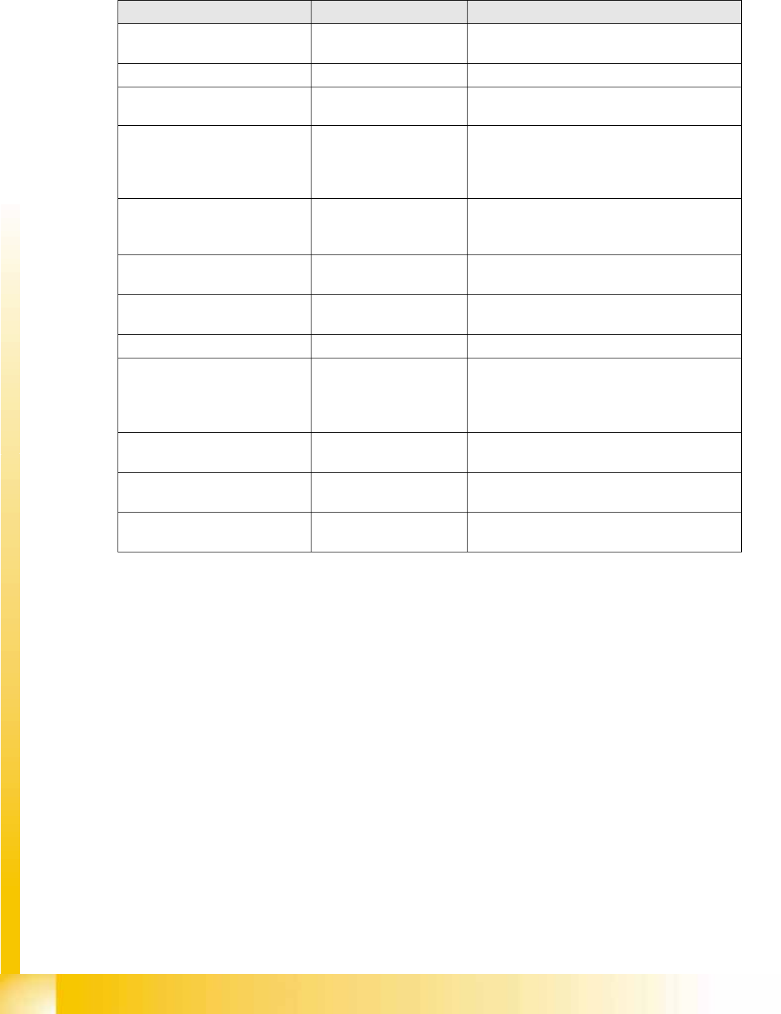
7.5.2 Overview of Spare Parts and Settings for C&P20A
Description (spare part) Tools Values
Component Camera Calibration component and
Allen wrench
Measuring the digital component camera.
Digital vacuum generator Caccia Firmware download possible
Read unit Z axis (not spare part) Feeler gauge 0.4 mm 0.4 mm between incremental encoder and
incremental scale.
Complete Z drive
Incremental encoder
Linear motor (for Siemens
service only)
Allen wrench During assembly, press the Z drive against the
stops.
Determining the star and Z zero point
correction.
Z axis return unit Move the return unit actuator to its end stop, so
that the Z axis is in the top position and the star
can be rotated.
Light barrier Z axis down (not
spare part)
Test probe 1.0 mm Distance 1.0 mm.
Component sensor (for Siemens
service only)
Check function
Firmware download possible
Silencer 10 mm open-end wrench None
Vacuum holding circuit, complete
Vacuum generator
Silencer
Special screw
10 mm open-end wrench
Allen wrench
Segment with DP drive Nippers with plastic tips
Allen wrench
Settings: none; firmware download possible;
calibrate segment offset (top, bottom).
Star carrier, complete (not spare
part)
Allen wrench Determining the star and Z zero point correction.
E/D transformer (collector ring),
comp. (for Siemens service only)
Allen wrench Determining the Z and star zero point correction.