00196044-05 - sg x und x4i fse_en.pdf - 第175页
Energy and Compressed Air Supply Subdistributor (X series from Ma No. B326) Power supply S tudent Guide (FSE) SIPL ACE X Series and X4I Edition 01/2009 EN Energy and Compressed Air Supply 175 5.2.3 Subdistributor (X ser …
Energy and Compressed Air Supply
Power supply Main distributor (X series from Ma. No. B326)
Student Guide (FSE) SIPLACE X Series and X4I
Energy and Compressed Air Supply Edition 01/2009 EN
174
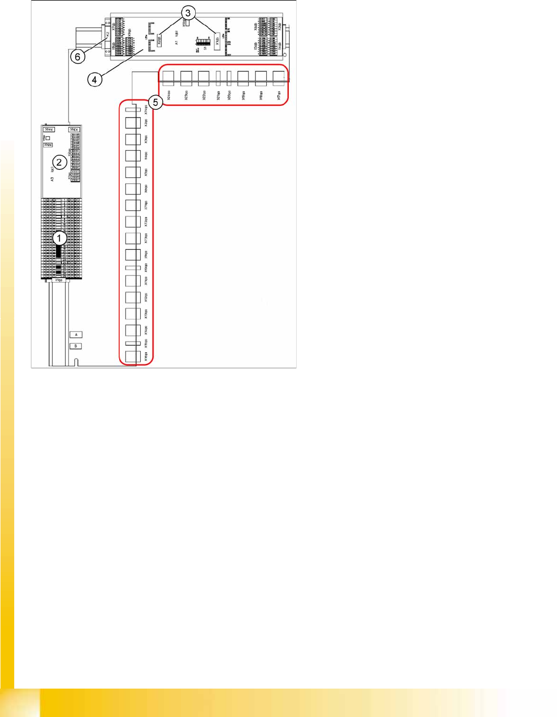
5.2.2 Main distributor (X series from Ma. No. B326)
5-3: Main distributor (X series from Ma. No. B326, X4I) [03046225-xx]
Legend:
1. Terminal strip X1qa (GND, +5 V, +15 V, -15 V,
+24 V, various signals)
2. DC/DC converter for illumination of all
cameras (PCB, component and stationary
cameras) in placement area 2
3. Socket for Interface 1-Wire CAT5
4. CAN-Bus I/O module (A1)
5. Connector block (connection X2qa - X6qa,
X71qa - X74qa and X9qa - X24qa)
6. Relay K2 switches the compressed air supply
for the placement heads off (can be configured
in the station software)
Energy and Compressed Air Supply
Subdistributor (X series from Ma No. B326) Power supply
Student Guide (FSE) SIPLACE X Series and X4I
Edition 01/2009 EN Energy and Compressed Air Supply
175
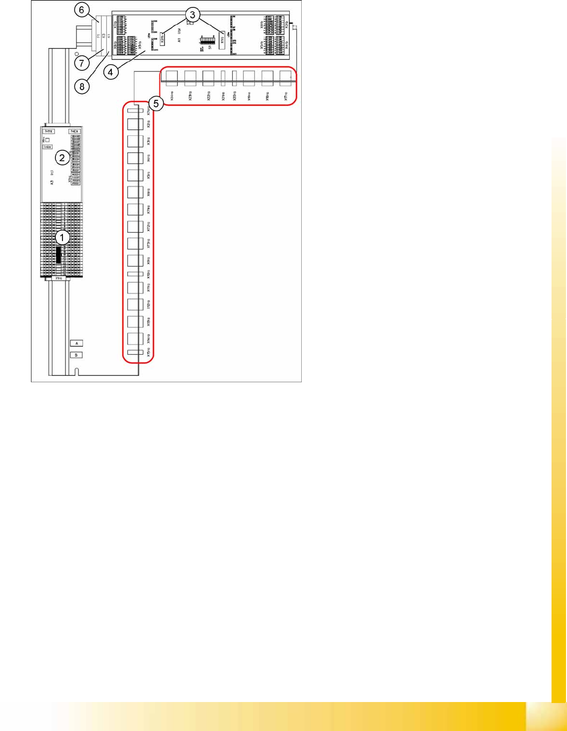
5.2.3 Subdistributor (X series from Ma No. B326)
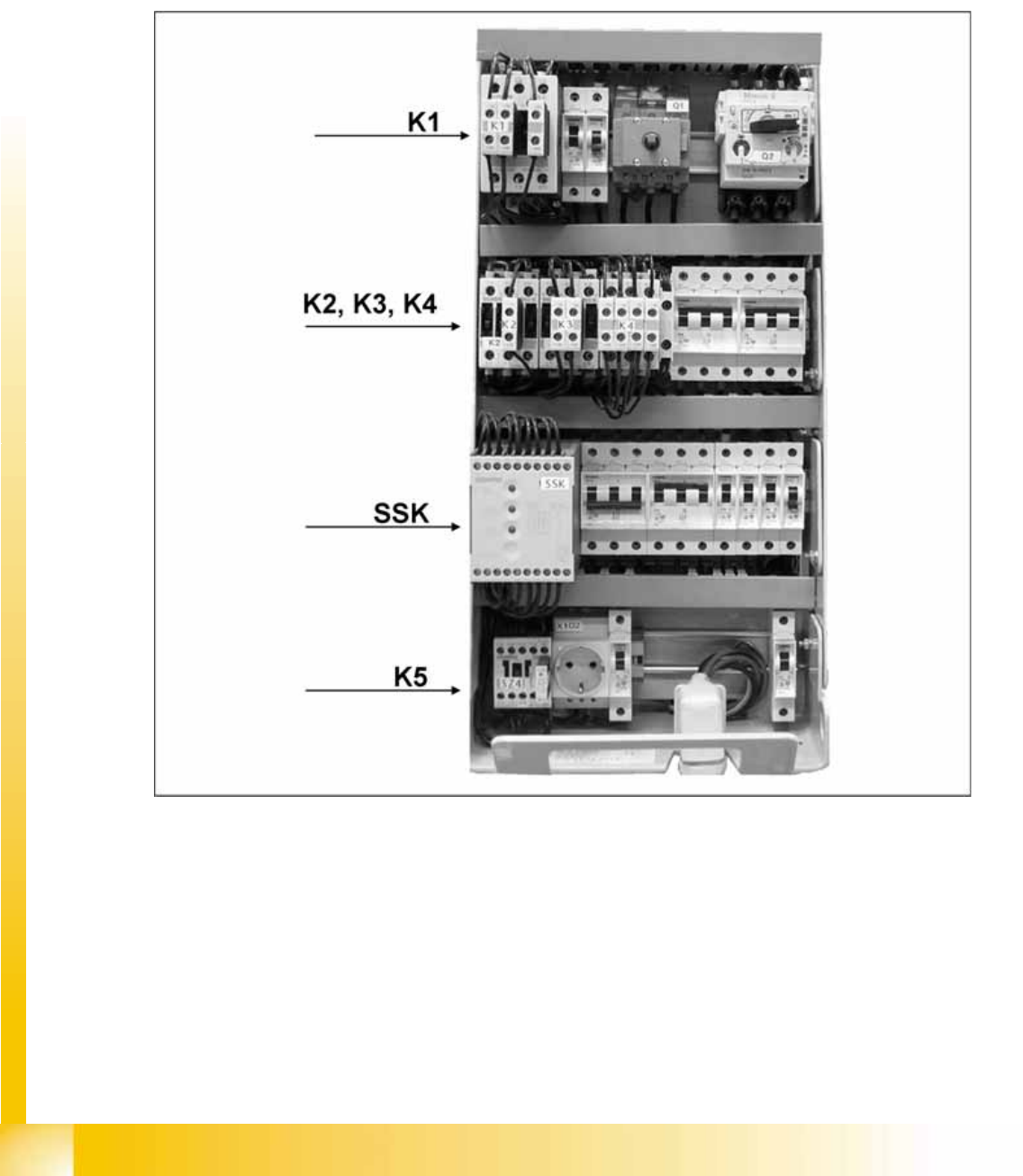
5.2.4 Power supply
The main power supply unit is mounted on a compact slide-in module, and located on the left side of the
machine. When viewed from the outside only the red main power switch is visible.
A lockable door prevents access to the power supply.
With the open cover, the state of the following protective devices can be quite easily monitored.
Motor Circuit Breaker
Main contactor
Safety relay
Power circuit breaker
Protective contactor combination (SSK)
5-4: Subdistributor (X series from Ma No. B326, X4I) [03046226-xx]
Legend:
1. Terminal strip X1ra (GND,+5 V,+15 V,-
15 V,+24 V,+52 V, various signals)
2. DC/DC distributor for illumination of all
cameras (PCB, component and stationary
cameras) in placement area 1
3. Socket for Interface 1-Wire CAT5
4. CAN I/O module (A1)
5. Connector block (connection X3ra - X6ra,
X71ra-X74ra, X10ra - X24ra)
6. F1: Fuse for the hood fan
7. K3: Relay for hood fan
8. K1: This relay switches the main valve in the
pneumatic unit.
Energy and Compressed Air Supply
Power supply Power supply
Student Guide (FSE) SIPLACE X Series and X4I
Energy and Compressed Air Supply Edition 01/2009 EN
176
The following work must be performed to adjust the power supply to the country-specific requirements
(see also the conversion instructions for power supplies):
1. Replace the motor protecting switch
2. Replace the power supply cable (country-specific)
3. At the primary end of transformer T1, the terminal connectors (U, V, W) must be reconnected to fulfill
the country-specific voltage requirements.
4. Reconnect the connector on the inrush limitation board transformer.
5-5: Main power supply
3 phase alternating power is supplied for operation of the SIPLACE X machines. N is only used for the
service socket. The contacts L1/L2/L3/N/PE are below the main power module. The phase L3 is also
fuse-protected for the server socket, via the F1 fuse.