00196044-05 - sg x und x4i fse_en.pdf - 第494页
Calibration Additional Functions Firmware Down load (SW 70x) S tudent Guide (FSE) SI PL ACE X Series and X4I Calibration Edition 01/2009 EN 498 12.6 Additional Functions 12.6.1 Firmware Downlo ad (SW 70x) X The function …
Calibration
Teaching Machine Positions - Placement Area Teaching Machine Positions
Student Guide (FSE) SIPLACE X Series and X4I
Edition 01/2009 EN Calibration
497
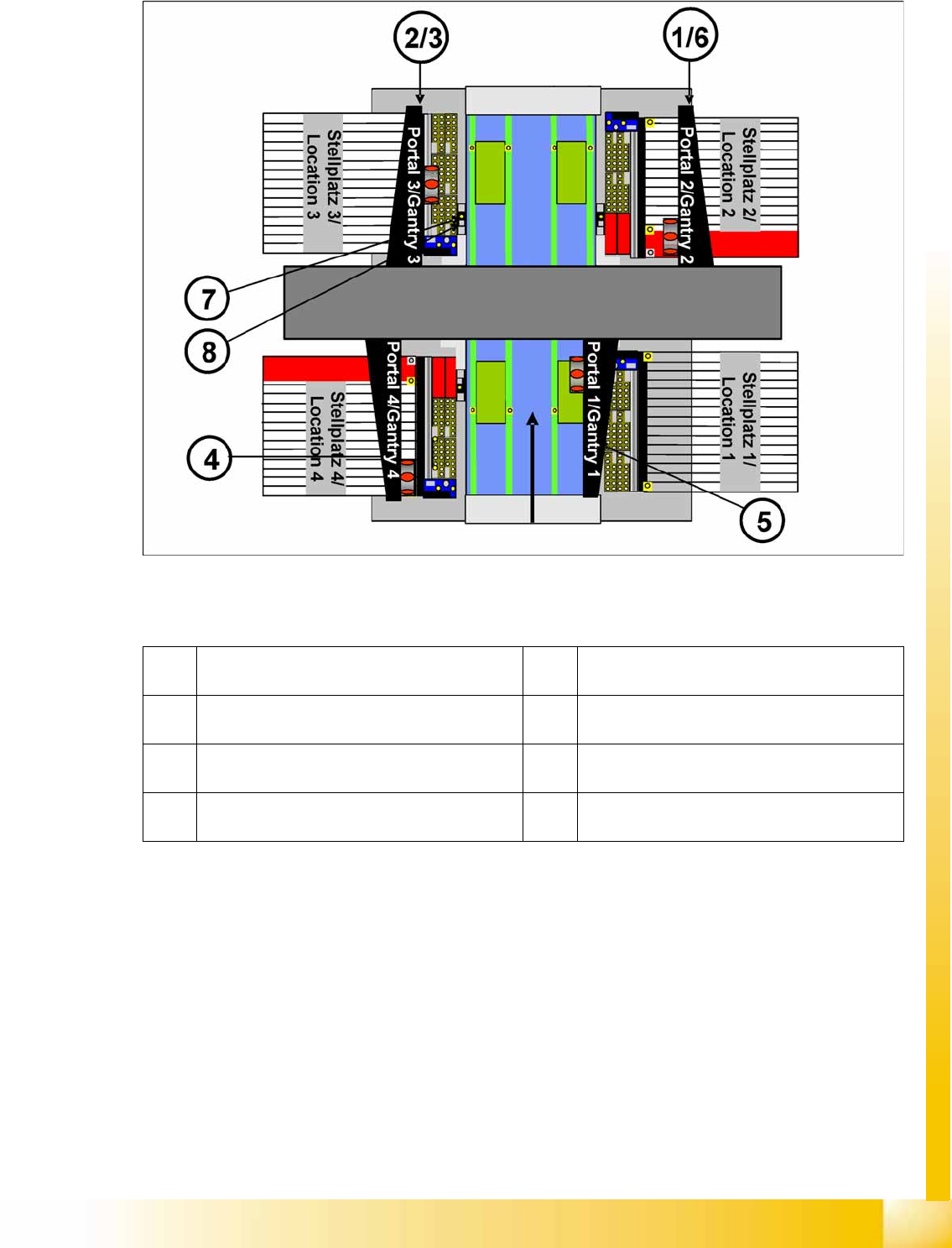
12.5.5 Teaching Machine Positions - Placement Area
This is where you can check and change the various machine positions.
Naming conventions, example of PA 1 gantry 1 :
(1) ProcessingArea_1: ParkPosition_R (park
position)
(2) ProcessingArea_1: RejectBox_R (component
reject position)
(3) Processing Area_1: RejectPosition_R
(component reject position)
(4) ProcessingArea_1: ServicePosition_R (service
position)
(5) ProcessingArea_1: SetupPosition_R (setup
change position)
(6) ProcessingArea_1: WaitPosition_R (waiting
position)
(7) ProcessingArea_1: ZeroOffsetFid (fiducial for
machine zero point)
(8) ProcessingArea_1: CalibrationPart5_Location
(calibration tool position for C&P20A head)
Calibration
Additional Functions Firmware Download (SW 70x)
Student Guide (FSE) SIPLACE X Series and X4I
Calibration Edition 01/2009 EN
498
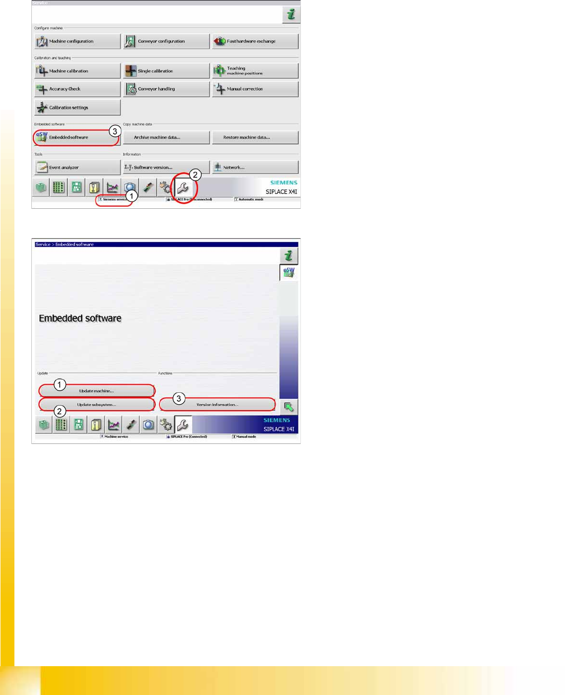
12.6 Additional Functions
12.6.1 Firmware Download (SW 70x)
X The function
Firmware Download
can be
performed with the user level (1)
Machine
service
or
Siemens service
.
X Switch over to the service menu (2).
X Click on
Embedded Software
(3).
1. Select this button to check the entire machine
and to perform an eSW download for multiple
subsystems.
2. Select this button to select and check one
subsystem, to perform an eSW download.
3. Select this button to view all versions of the
subsystems, BIOS application 1/2.
Calibration
Head Exchange SIPLACE X Additional Functions
Student Guide (FSE) SIPLACE X Series and X4I
Edition 01/2009 EN Calibration
499
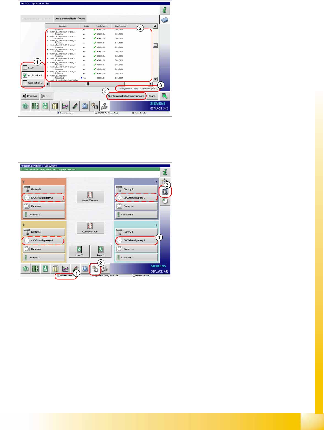
12.6.2 Head Exchange SIPLACE X
Head data
1. Selection button, BIOS application1/2
2. Shows the status of the individual subsystems.
3. Update information about the number of
subsystems which still have to be
downloaded.
4. Starts the download.
After changing the head hardware, the new head
data needs to be made available from the head
EPROM of the software.
X Switch the machine on.
X Select the user level
Service (customer)
(1).
X Switch over to the menu
Check sensors and
functions
(2).
X Click on the
Check sensors and functions of
specific components
(3).
X Click on
CP20 head, gantry x
button for the
gantry concerned (4).