00196044-05 - sg x und x4i fse_en.pdf - 第210页
Gantry Overview Mechanical Structure of X and Y Axes S tudent Guide (FSE) SI PL ACE X Series and X4I Gantry Edition 01/2009 EN 210 6.1.1 Mechanical Struct ure of X and Y Axes Please Note: X and Y Axes have the same basic…
Gantry
Overview
Student Guide (FSE) SIPLACE X Series and X4I
Edition 01/2009 EN Gantry
209
6Gantry
6.1 Overview
The gantries of the SIPLACE X machines consist of one X and one Y axis. Both axes are driven by a
linear motor which is equipped with an integrated temperature sensor. These temperature sensors only
monitor the motor coils. Viewed from the direction of transport, the Y motors move from the right to the
left, in a more positive direction (new coordinate system) and the X motors move from the input conveyor
to the output conveyor, in a more positive direction. The coordinate origin is exactly in the center of the
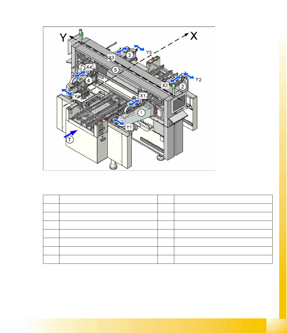
machine. The placement heads are mounted on the head plates of the respective X axis.
6-1: Position of the gantries in the X4I machine
Legend
X X axis – positive direction of travel Y Y axis – positive direction of travel
1 Gantry 1 in placement area 1 3 Gantry 3 in placement area 2
X1 X axis, gantry 1 X3 X axis, gantry 3
Y3 Y axis, gantry 1 G3 Y axis, gantry 3
2 Gantry 2 in placement area 2 4 Gantry 4 in placement area 1
X2 X axis, gantry 2 X4 X axis, gantry 4
Y2 Y axis, gantry 2 Y4 Y axis, gantry 4
T Transport direction 5 Coordinate origin
Gantry
Overview Mechanical Structure of X and Y Axes
Student Guide (FSE) SIPLACE X Series and X4I
Gantry Edition 01/2009 EN
210
6.1.1 Mechanical Structure of X and Y Axes
Please Note: X and Y Axes have the same basic mechanical parts.
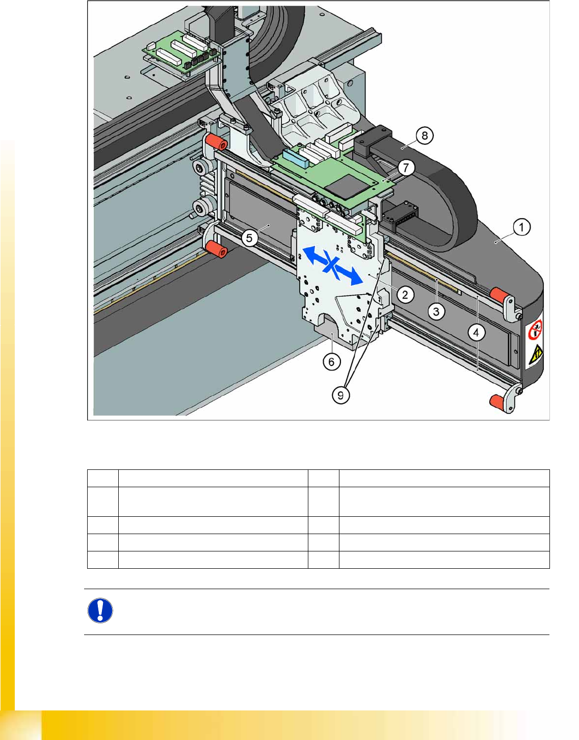
6-2: Mechanical structure "Gantry"
Legend
1 X gantry made of carbon fiber 6 PCB camera mounted under the gantry
2 Head mounting plate with integrated primary
part of X axis linear motor
7 Boards (head interface with Vision board below -
vertical - the head adapter board)
3 Incremental scale 8 X trailing cable
4 Linear guidances for X axis (above/below) 9 Temperature sensors
5 Secondary part X axis (magnet)
NOTE:
To improve placement accuracy, the temperature sensors compensate the offset between the
PCB camera and the nozzle, based on the temperature of the head mounting plate.
Gantry
Reference Run Sequence at X and Y Axis (A364) Gantry Reference Run (with A364)
Student Guide (FSE) SIPLACE X Series and X4I
Edition 01/2009 EN Gantry
211
6.1.1.1 Description
The head mounting plate with the placement head is moved in the X direction by the linear guidances,
which are mounted above and below the secondary part of the linear motor. The Y axis moves the entire
X axis gantry with the placement head.
For X and Y axis position recognition we use incremental metal scales. These are positioned above the
secondary part for the X axis and below the secondary part of the Y axis. An incremental encoder reads
the increments, which are then sent to the axis controller boards, for determination of the axis positions
and for motor control.
Each X and Y axis has a rubber bumper as hardware stop at its ends.
6.2 Gantry Reference Run (with A364)
6.2.1 Reference Run Sequence at X and Y Axis (A364)
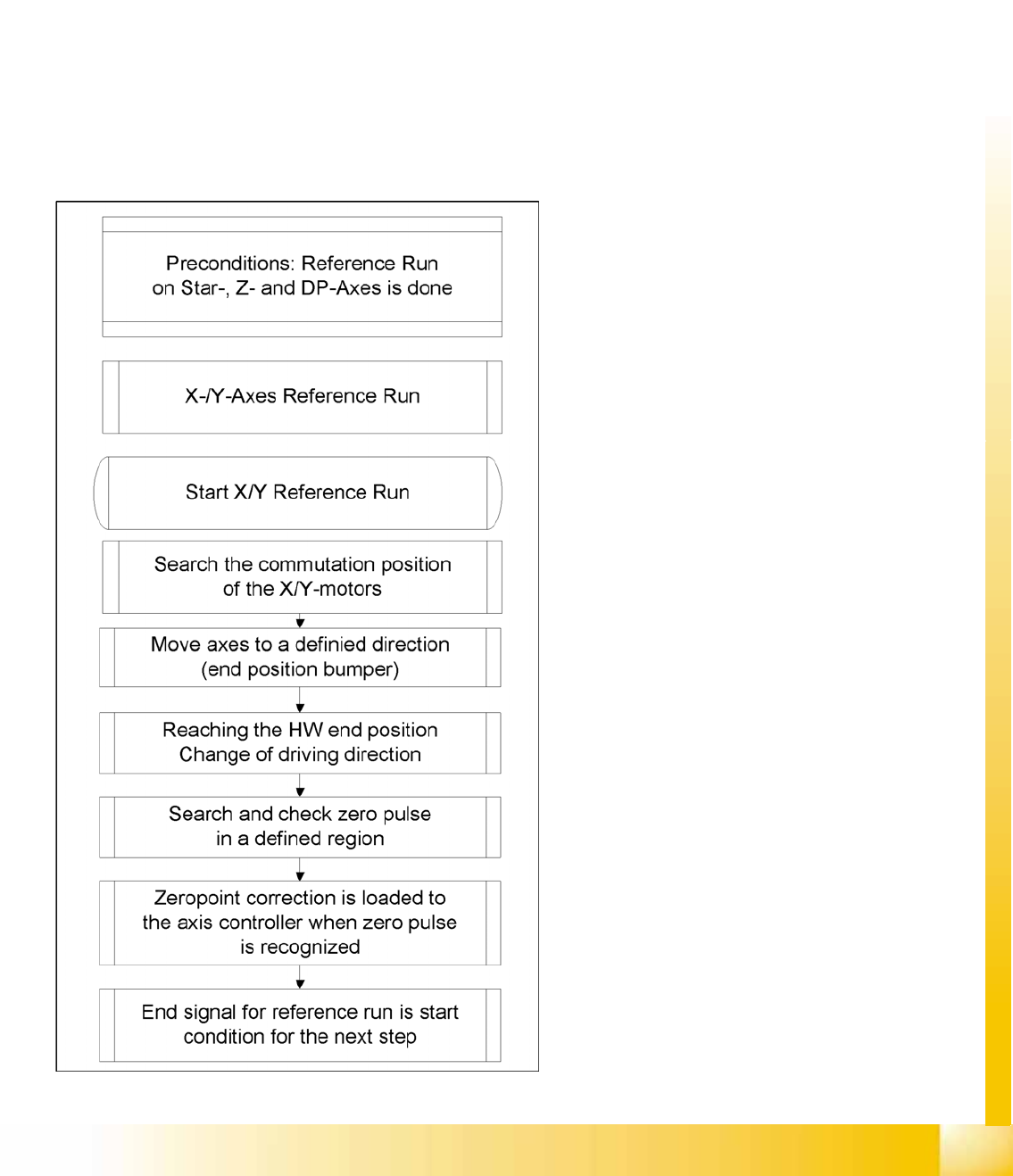
6-3: Reference run sequence
After the commutation search, the motor is in an
undefined position for the control system. When
referencing with bumper recognition (hardware
end stops), the axis moves successively against
the bumpers. For this purpose, fixed target values
are set by the axis controller, which are
increasingly nearer to the mechanical end stop.
After a certain time, this approach function
reaches a state in which the set target position is
no longer reached (actual position ≠ target
position, the axis is at the hardware end stop
(bumper)).
After a certain time (approx. 10 ms) and after
reaching a certain motor current, the direction of
travel is reversed and the axis searches for the
zero pulse within a specified range. This zero
pulse must be found within a predefined travel
range. If the zero pulse has been found in this
area, further zero pulses will be searched for in an
area of approx. 2.5 mm
After reaching and checking the zero pulse, the
axis is in a defined position.
The reference run for the main axes is started
simultaneously at all 4 gantries.