00196044-05 - sg x und x4i fse_en.pdf - 第306页
Collect, Pick and Place Head (CPP) Overview Overvi ew of Parts S tudent Guide (FSE) SI PL ACE X Series and X4I Collect, Pick and Place Head (CPP) Edition 01/2 009 EN 306 8.2.7.4 Return unit Retract Unit Functions At zero…
Collect, Pick and Place Head (CPP)
Overview of Parts Overview
Student Guide (FSE) SIPLACE X Series and X4I
Edition 01/2009 EN Collect, Pick and Place Head (CPP)
305
The secondary part with the magnets is part of the Y axis and the primary part is fixed. Benefit, there
are no moveable cables for supplying power to the motor.
The jaws are installed on the secondary part of the Z motor, for mechanical docking of the DP drives.
This return unit keeps the Z axis in the safe, upper position during zero current.
The Z drive forms a complete unit, together with the head front plate, jaws, raceway, measuring
system and return unit. Do not remove or replace individual parts of this unit, as precise settings are
required for each part.
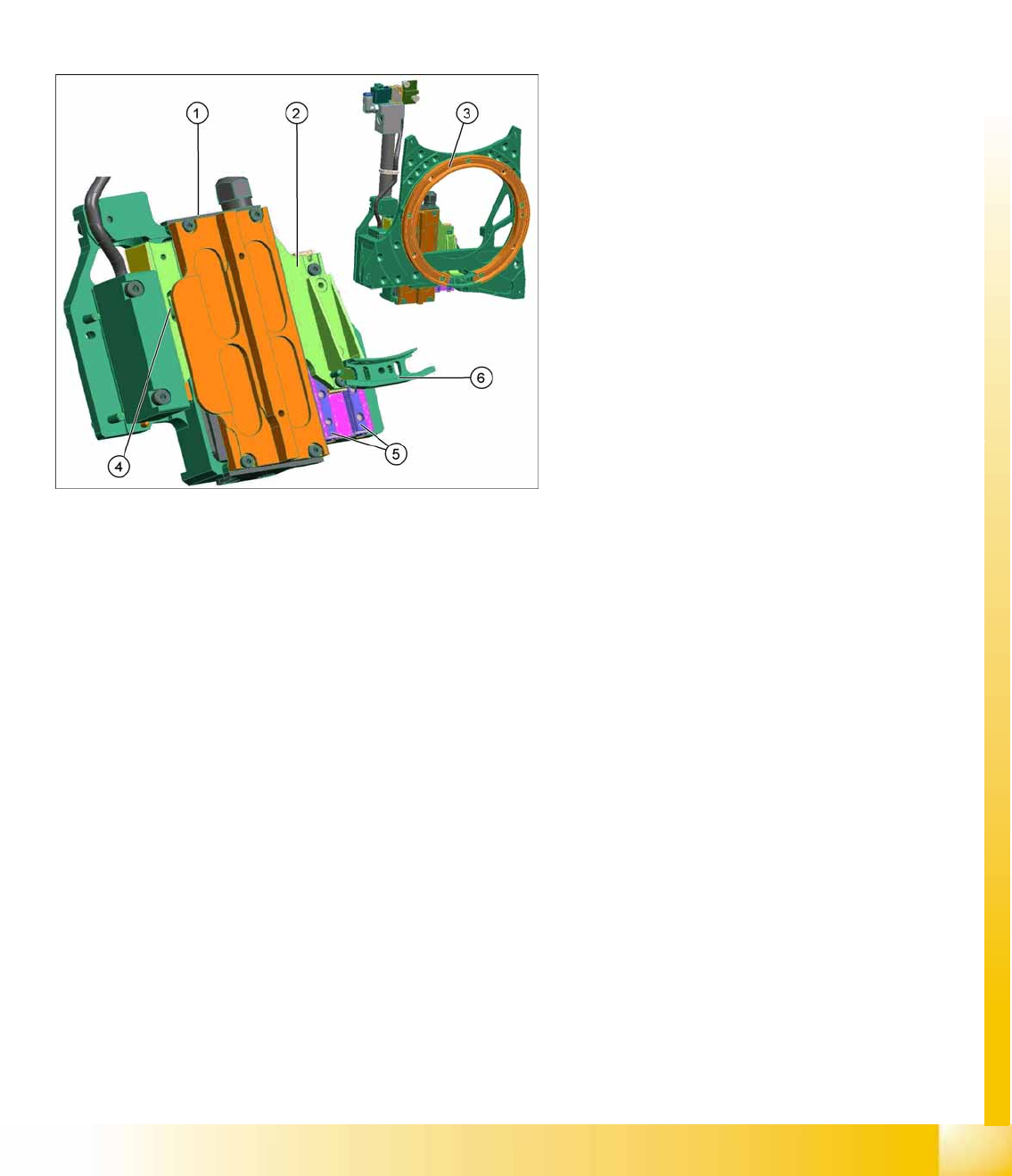
Z Drive Function
The Z drive is a 3 phase linear motor. The moveable part (magnets) is guided on the one side via
two linear guidances and, on the other side, through a support roller.
The incremental measuring system is located on the side with the support roller.
Each Z drive has an EEPROM, in which the following data is stored:
– Production data (manufacturer, serial number, ...)
– Operating data (errors, travel cycles, ...)
– Machine data (motor data, travel profiles, zero point correction, max. and min. position)
The measuring system has a resolution of 0.5 µm. The zero pulse is approx. 2 mm under the top
stop.
New servo amplifier for A364 SDS120/1.5Z2
Legend
1. Z motor, primary part
2. Z motor, secondary part
3. Raceway
4. Support roller
5. Linear guidance Z axis
6. Snap jaws
Collect, Pick and Place Head (CPP)
Overview Overview of Parts
Student Guide (FSE) SIPLACE X Series and X4I
Collect, Pick and Place Head (CPP) Edition 01/2009 EN
306
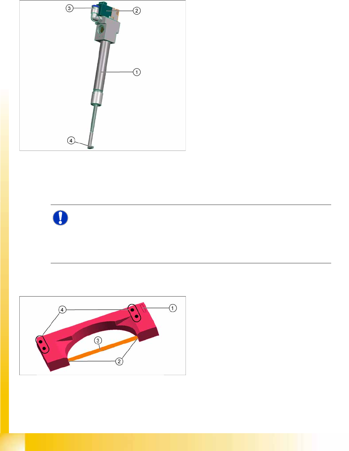
8.2.7.4 Return unit
Retract Unit Functions
At zero current, the bearing friction of the Z axis is not sufficient to protect the axis from falling down. A
pneumatic return system has been installed to protect the Z axis should the gantry be moved when the
machine is switched off. This return unit keeps the Z axis in the safe, upper position during zero current.
8.2.7.5 Component sensor
Each CPP head is fitted with a component sensor in the pickup/place position, as a standard. This
component sensor monitors the presence and/or component height after pickup and before placement.
The sensor is fixed to the head with two screws and can be replaced as a complete unit during service
work.
Legend
1. Pneumatic cylinder
2. Solenoid valve
3. Compressed air connection
4. Z axis driver
The return unit is fixed to the Z axis. This return
unit keeps the Z axis in the safe, upper position
during zero current. This ensures that the
placement head is not damaged when the
machine is switched off or in the event of a power
cut.
The return unit is not a spare part and can only be
replaced together with the complete front plate of
the head.
NOTE:
The Z axis control system is designed to ensure that, should the machine power supply fail (or
be switched off), there is always enough power temporarily stored by the Z motor servo unit and
axis controller board to move the Z axis to the upper position.
Power failure is recognized by the issuance of a "Power fail" signal. This "Power fail" signal
enables the relevant function (upwards movement of Z axis and activation of the return unit) on
the axis controller board.
Legend
1. Power/data supply connector
2. Transmitter and receiver unit
3. Laser beam
4. Fixture to head casing
(2x centering pins, 2x screws)
Collect, Pick and Place Head (CPP)
Overview of Parts Overview
Student Guide (FSE) SIPLACE X Series and X4I
Edition 01/2009 EN Collect, Pick and Place Head (CPP)
307
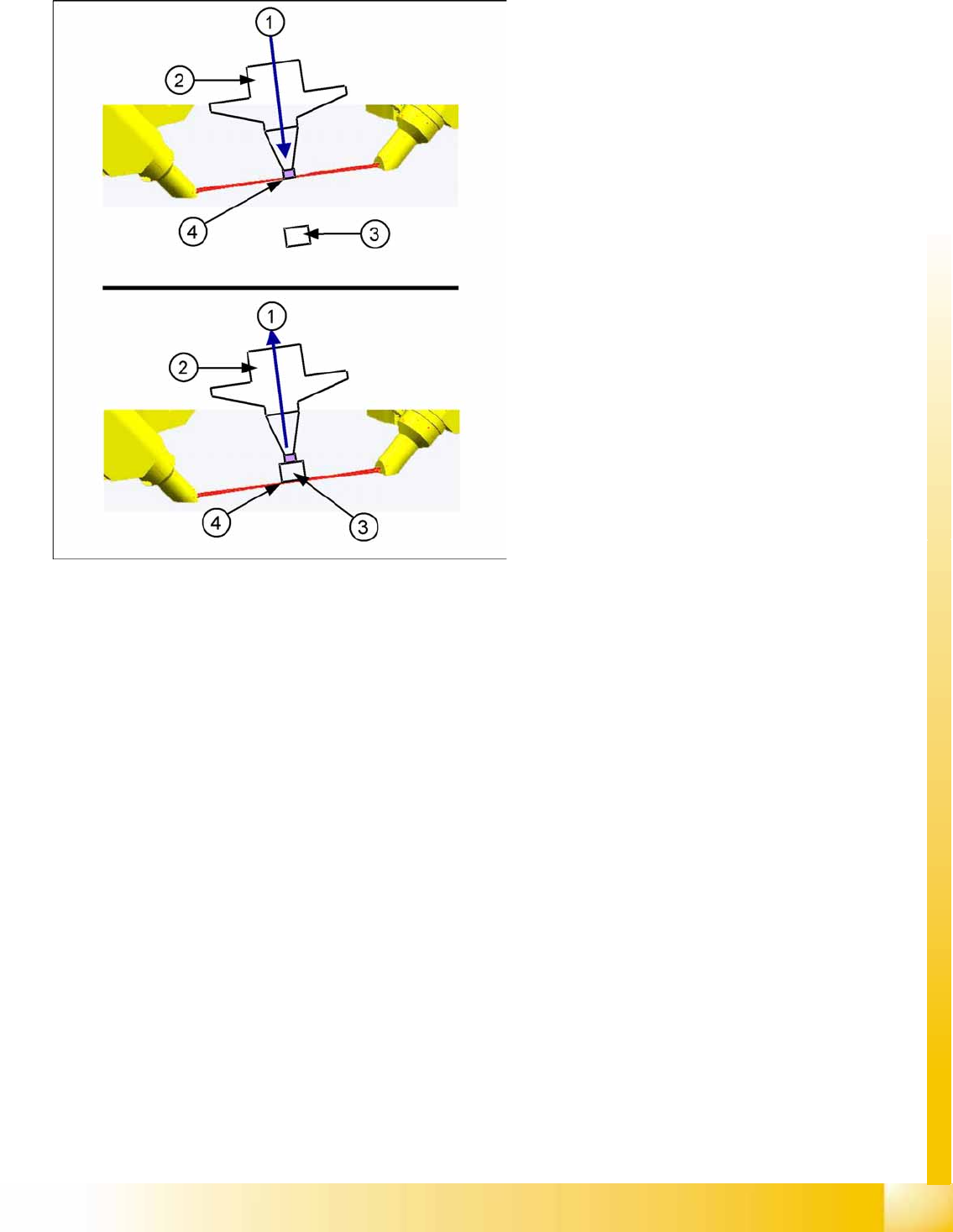
Component Sensor Functions
Pickup Process:
When the Z axis moves downwards, the nozzle interrupts the IR beam. At this exact moment, this Z axis
position is recorded and compared to the reference value, from the height reference run, or from this
segment after placement. This determines whether there is still a component on the nozzle or not. If the
Z axis position indicates that there is a component on the nozzle, the Z axis will be immediately stopped.
An error message will appear or the component will be rejected and added to the repair cycle as not
placed.
When the Z axis moves upwards again, the laser beam is released and the Z position recorded. Based
on the Z position during downwards movement, the system can now determine the presence and height
of a component.
Placement Process:
During the placement process, the system checks whether the component is at the nozzle (Z downwards
movement) or whether placement has been performed on the component (Z upwards movement). As a
precaution, these Z positions are compared to those from the pickup procedure.
This ensures maximum pickup and placement reliability.
Legend
1. Downwards (top diagram) or upwards (bottom
diagram) movement
2. Nozzle
3. Component
4. Read out Z position, if the IR beam is
interrupted (top diagram) or has been released
again (bottom diagram).
The component sensor signal is directly linked to
the axis controller (measurement system) of the Z
axis. This enables you to read out the Z position
during upwards and downwards movement.