00196044-05 - sg x und x4i fse_en.pdf - 第216页
Gantry Settings PCB Boards on the Gantry S tudent Guide (FSE) SI PL ACE X Series and X4I Gantry Edition 01/2009 EN 216 LEDs on the Head Interface 6-8: Head interface with status LED s LED H1-H6,H17,H18 (func tional check…
Gantry
PCB Boards on the Gantry Settings
Student Guide (FSE) SIPLACE X Series and X4I
Edition 01/2009 EN Gantry
215
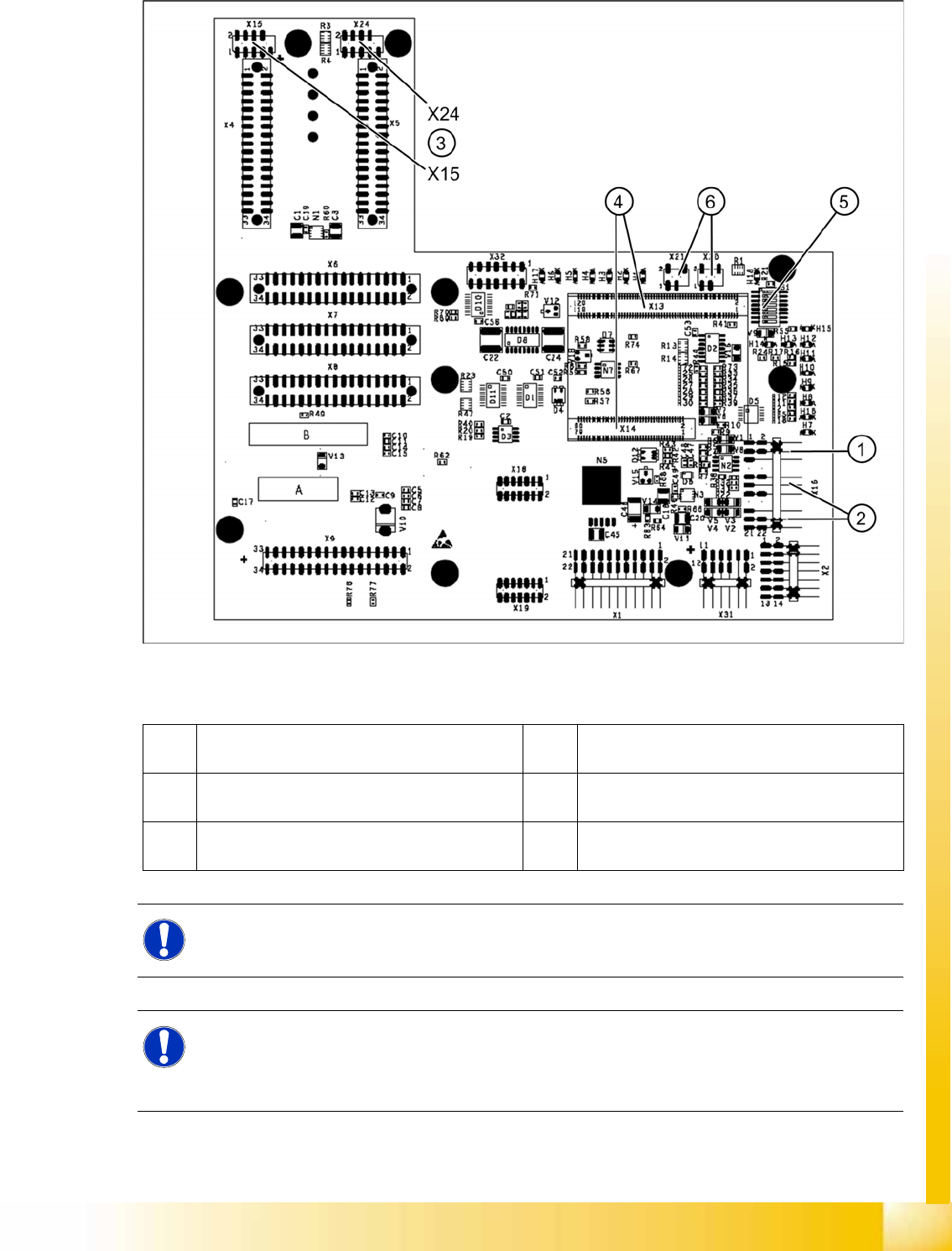
6.3.2.1 Head Interface C500
6-7: Head interface (C500)
Legend
1 X16 temperature sensor for X axis 4 X13 / X14 connector for 16 Bit processor board
(TQM module)
2 Proximity switches for X axis travel range (not
with A364)
5 DIP switch
3 X15 connector for incremental encoder X axis
(X24 connector digital track signals X axis)
6 X20/X21 both connections can be used for the
temperature sensors.
NOTE:
The DIP switch configuration for the gantry configuration is described in chapter Gantry.
NOTE: X4I
In SIPLACE X4I machines, a mirrored version of the C500 head interface is used on gantries 2
and 4.
X Note the different item number!
Gantry
Settings PCB Boards on the Gantry
Student Guide (FSE) SIPLACE X Series and X4I
Gantry Edition 01/2009 EN
216
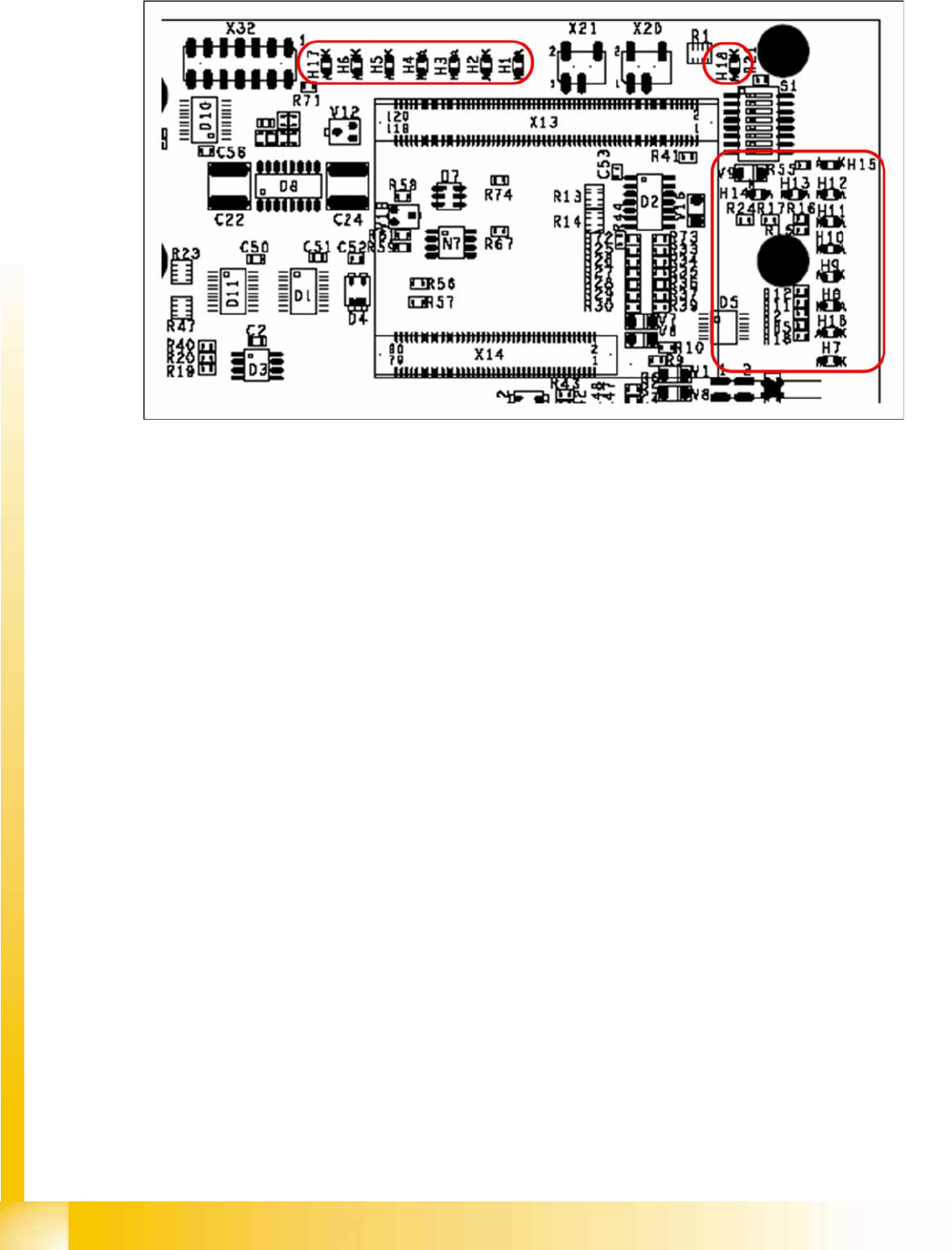
LEDs on the Head Interface
6-8: Head interface with status LEDs
LED H1-H6,H17,H18 (functional check)
H17 SPI - Serial parallel interface (Test)
H6 D-ON - digital ON 5V DC/DC converter (power supply head interface, generated from the 24V)
H5 H-OK - Head adapter board connected
H4 C-In - CAN Internal (status off)
H3 MRST - Main Reset (always off)
H2 F-UC – Failure - UC test
F-UC flashes red after switching on the machine:
- eSW unable to perform one or more functions or initialization of a subsystem.
- flashes while the production power fail signal is active or 15 V missing.
H1 MP - Main Power fail, mean 5 V power supply being missing at the machine (e.g. CAN Bus)
H18 1 Wire LED shows the high level on PIN 1 of 5V ON is green --> OK
LED H7- H15, H1B (LEDs for voltages)
H14 Vcc - shows the output signal of the DC/DC converter (H6) +5 V
H13 N15V – -15 V for Twin Head --> force measurement board (not for X4I)
H15 P3,3V - Controller OK
H12 P15V - Plus 15 Volt light barrier bottom C&P head
H11 P24V - 24 V power supply (e.g.stepping motor)
H10 AV ER - Failure 5 V
H9 EN AN – 16 bit processor connected --> supply voltage OK
H8 P5V - 5 V power supply track signals X axis --> red LED ON at error
H1 B P5V – 5 V power supply for digital switching --> outside tolerance
H7 X-Temp - Temperature monitoring X axis
Gantry
PCB Boards on the Gantry Settings
Student Guide (FSE) SIPLACE X Series and X4I
Edition 01/2009 EN Gantry
217
DIP Switches on the Head Interface
* Not all gantries may be available, depending on the machine type.
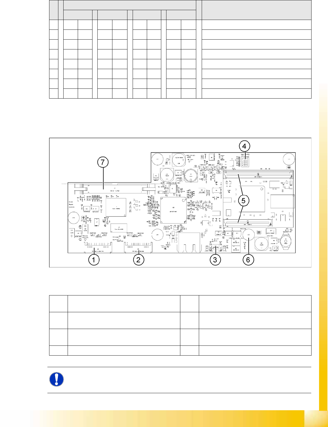
6.3.2.2 Vision Board (Digital Version 02)
The Vision processor board is fixed to the head interface of each gantry.
6-9: Vision board
Legend
S Setting for gantry* Comments
1 2 3 4
1 OFF ON OFF ON P0 – gantry ID0 address switch 1 --> gantry
2OFF OFF ON ONP1 – gantry ID1 address switch 2 --> gantry)
3XX XX XX XXOFF: Twin Head – ON: C&P head
4 OFF OFF OFF OFF Boot
5 OFF OFF OFF OFF Reset – CAN processor, 16 bit (TQM module)
6 OFF OFF OFF OFF CAN_ID0
7 OFF OFF OFF OFF CAN_ID1
8 OFF OFF OFF OFF WP_EEPROM
1 X8 Connector illumination and video signals
PCB camera
5 CAN processor 16 Bit (TQM module)
2 X3 Connector illumination and video signals
component camera
6 DC/DC converter 15 --> 5V for Vision system.
3 LED‘s P15V - 15Volt / Vcc - Power supply Vision
board
7 Connector X4 – connection for video signals to
trailing cable
4 DIP switch
NOTE:
The DIP switch configuration for the gantry configuration is described in Section (6.3.2.4 Check
the DIP Switches
J
219 ) .