00196044-05 - sg x und x4i fse_en.pdf - 第116页
Communication and Control CAN Bus Communication SIPLACE Vision S tudent Guide (FSE) SI PL ACE X Series and X4I Communication and Control Edition 01/2009 EN 11 6 4.3.6.1 Communication During Image Acquisition The main com…
Communication and Control
Communication SIPLACE Vision CAN Bus
Student Guide (FSE) SIPLACE X Series and X4I
Edition 01/2009 EN Communication and Control
115
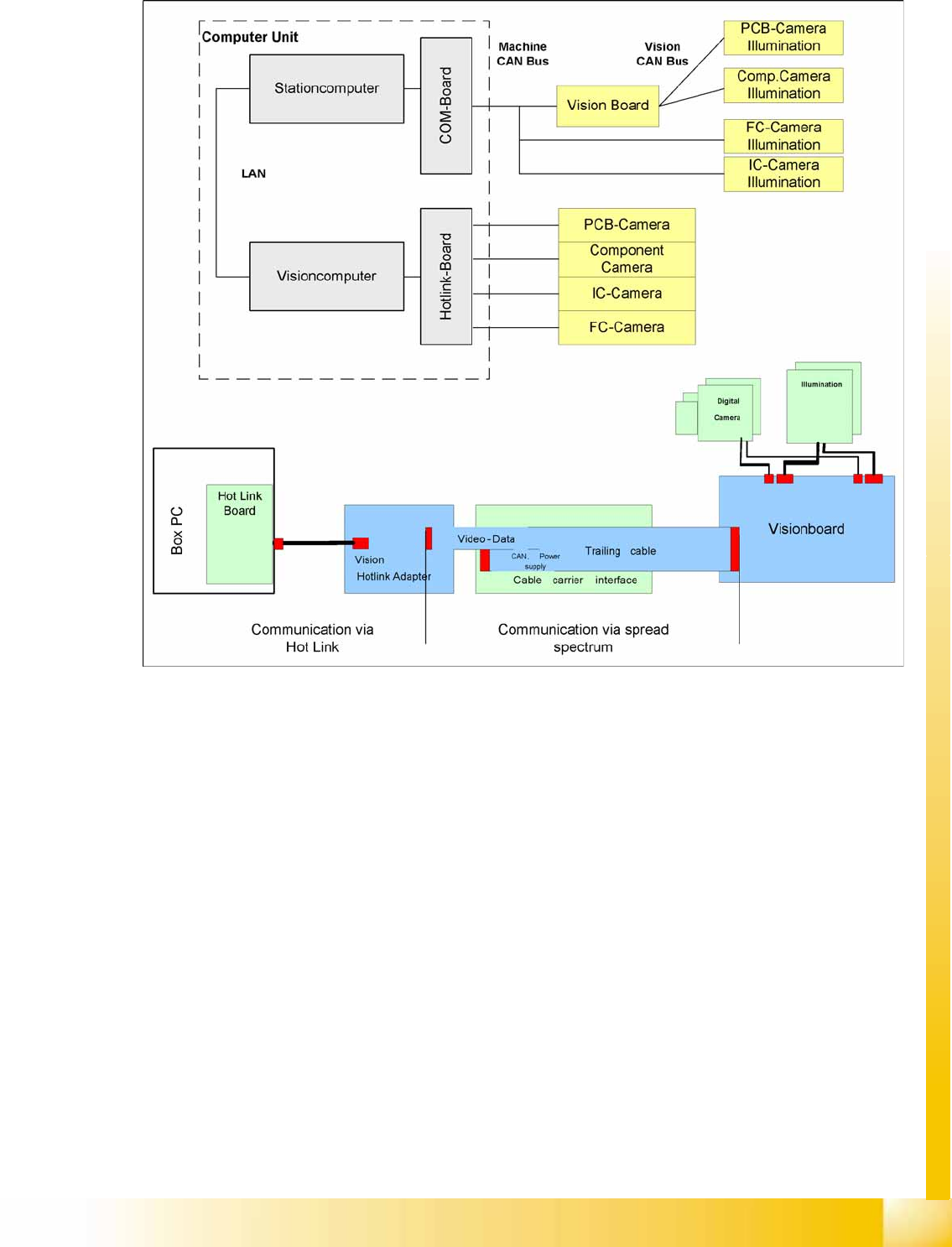
4.3.6 Communication SIPLACE Vision
4-25: Overview SIPLACE Vision
The communication between the computers is via LAN cables. The station computer sends the
commands for image acquisition to the Vision computer and receives the measurement result. The
station computer also sends the illumination values for the respective component shapes. The images
recorded are transferred digitally via the Vision board to the hotlink adapter, using the spread spectrum
and are then sent via the hotlink connection to the Vision computer, for evaluation. The result is sent to
the station computer.
Communication and Control
CAN Bus Communication SIPLACE Vision
Student Guide (FSE) SIPLACE X Series and X4I
Communication and Control Edition 01/2009 EN
116
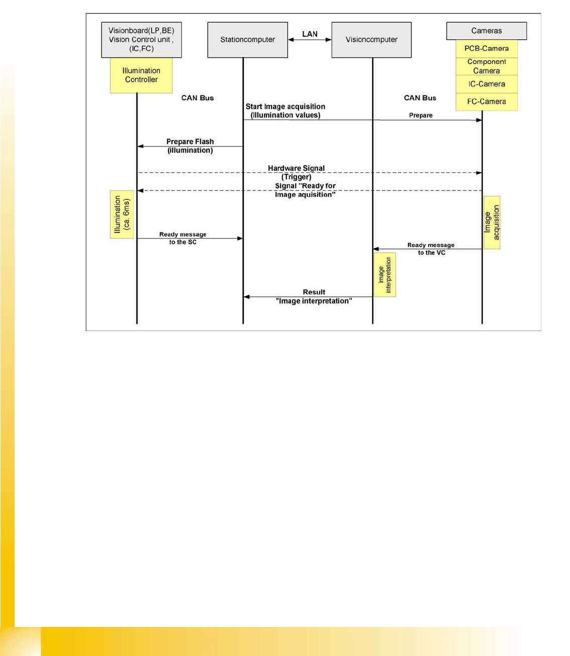
4.3.6.1 Communication During Image Acquisition
The main communication between the Vision system and station computer is the transmission of
illumination values. These values, stored in the CS, are sent via CAN bus to the camera in question. As
soon as the camera should take the picture, the camera illumination is activated by a trigger. From this
moment on the row of LEDs which provides the different illumination levels shines according to the
illumination value. This illumination value can have 0 = dark up to 255 = bright. All illumination levels start
lighting at the same moment. The value 0-255 determines the length of the illumination time.
The maximum length of illumination is limited to 6 ms.
4-26: Time sequence from up to down for image acquisition communication
Communication and Control
Communication DP Drives, C&P20A and CPP Head CAN Bus
Student Guide (FSE) SIPLACE X Series and X4I
Edition 01/2009 EN Communication and Control
117
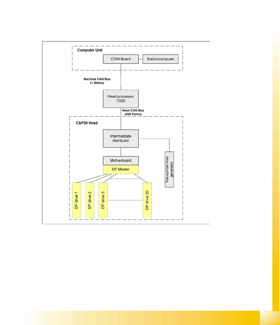
4.3.7 Communication DP Drives, C&P20A and CPP Head
The TQM module on the head interface C500 communicates via the CAN Bus (1M/Bit/s) with the station
computer.
The communication to the C&P20A or CPP head is via an additional CAN Bus, which sends the data
with 500 KBit/s.
The DP axes are controlled via the DP master (SCS). 4 actions are performed by the machine control at
the same time:
Starts a certain rotary axis after pickup/placement (pickup angle/placement angle)
Starts a certain rotary axis after Vision (correction angle)
Waits for a certain rotary axis before Vision (positioning command not allowed)
Waits for a certain rotary axis before pickup/placement (positioning command not allowed)
4-27: CAN Bus-controlled head functions on the C&P20A head