00196044-05 - sg x und x4i fse_en.pdf - 第244页
C&P20A Overview Parts Overview with Function Description S tudent Guide (FSE) SI PL ACE X Series and X4I C&P20A Edition 01/2009 EN 244 7.2.3.5 St ar Assembly St ar carrier The mechanical E/D transformer (1) consi…
C&P20A
Parts Overview with Function Description Overview
Student Guide (FSE) SIPLACE X Series and X4I
Edition 01/2009 EN C&P20A
243
Component Sensor Functions
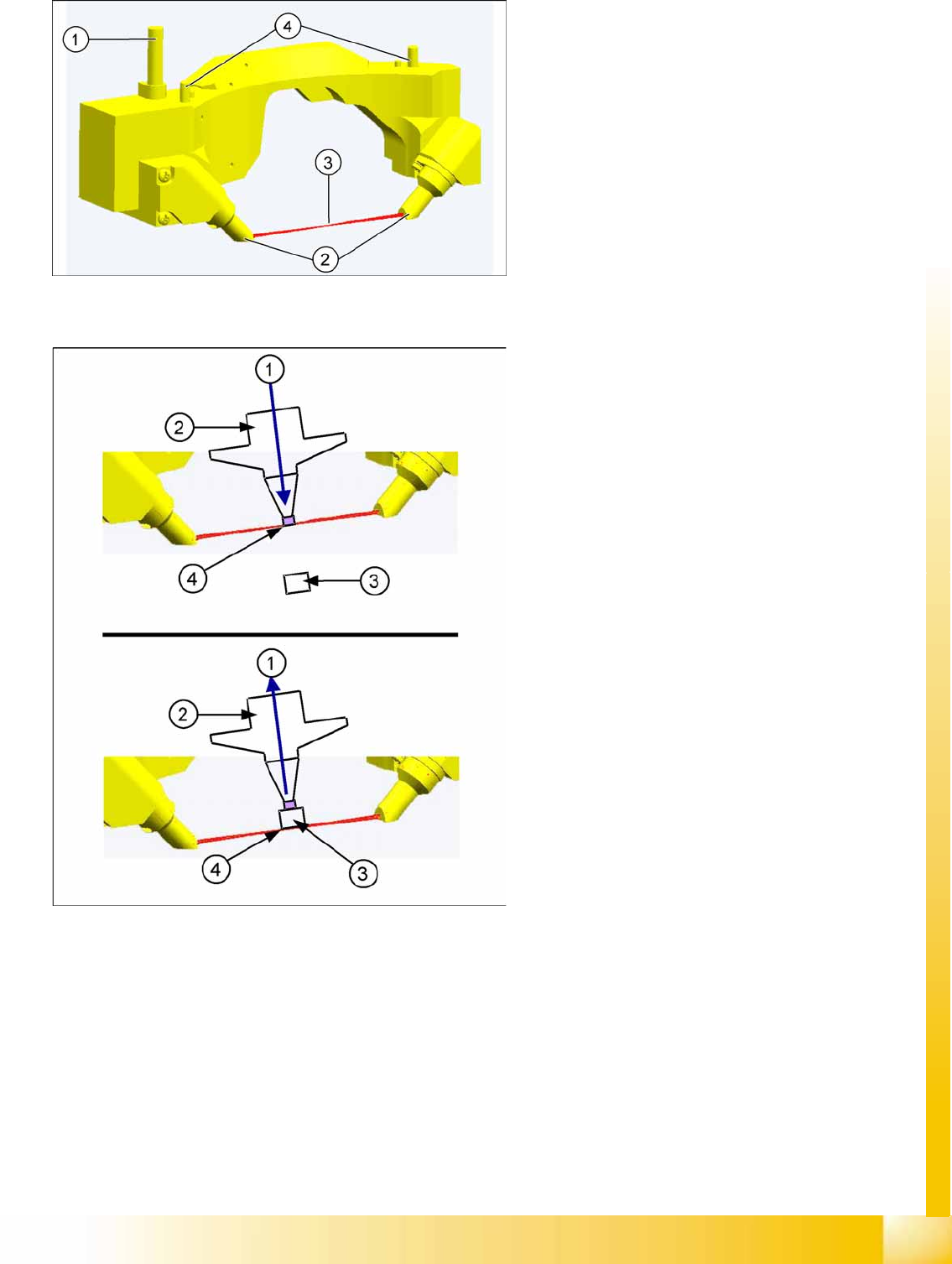
Pickup Process:
When the Z axis moves downwards, the nozzle interrupts the laser beam. At this exact moment, the
Z axis position is recorded and compared to the reference value, to see whether there is still a
component on the nozzle. If the Z axis position indicates that there is a component on the nozzle,
the Z axis will be immediately stopped. An error message will be issued or the component will be
rejected. When the Z axis moves upwards again, the laser beam is released and the Z position
recorded. Based on the Z position during downwards movement, the system can now determine the
presence and height of a component.
Placement Process:
During the placement process, the system checks whether the component is at the nozzle/whether
placement has been performed on the component.
Component sensor
In its standard state, the component sensor is
installed in the pickup-placement position on
the C&P20A head.
The sensor is fixed to the head with two
screws and can be replaced as a complete unit
during service work.
Legend
1. Power/data supply cable
2. Transmitter and receiver unit
3. Laser beam
4. Fixture to housing
Legend
1. Downwards (top diagram) or upwards (bottom
diagram) movement
2. Nozzle
3. Component
4. Read out Z position, if the IR beam is
interrupted (top diagram) or has been released
again (bottom diagram).
The component sensor determines the
component and nozzle height during the
placement process.
The component sensor signal is directly linked to
the measurement signal of the Z axis incremental
encoder.
C&P20A
Overview Parts Overview with Function Description
Student Guide (FSE) SIPLACE X Series and X4I
C&P20A Edition 01/2009 EN
244
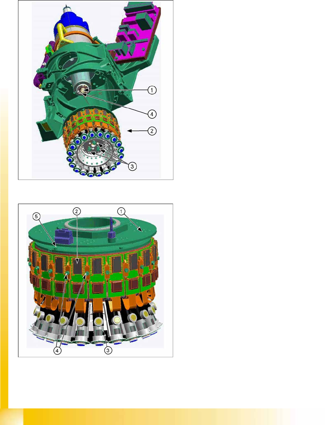
7.2.3.5 Star Assembly
Star carrier
The mechanical E/D transformer (1) consists of a stationary and a rotating part. The 6 sliding contacts
transmit direct voltage (24V/4A), ground and CAN bus signals (CAN high, CAN low). The E/D
transformer can be replaced during service work.
E/D transformer (collector ring) (03007834-0x]
Legend
1. Motor shaft (1)
2. Star Assembly
3. Screws (3) mounting the star unit to the motor
shaft
4. Smoothed distributor disc
The star consists of the star carrier, on which the
20 DP drives are located, the motherboard and the
E/D transformer.
This complete unit is fixed to the motor shaft with
three screws and can be removed for service work
after the raceway has been dismounted.
Above the star you will find the E/D
transformer (1) for supplying energy and data
to the DP drives.
The motherboard is located behind the control
boards (2) of the DP drives (3) and is
responsible for controlling and positioning the
DP drives.
The control board is plugged into the
motherboard and is fixed via the two brackets
(4).
Two screws fix the complete DP drive unit from
inside, to the star frame.
An index screw (5) ensures that the ED
transformer is correctly positioned during
assembly.
C&P20A
Parts Overview with Function Description Overview
Student Guide (FSE) SIPLACE X Series and X4I
Edition 01/2009 EN C&P20A
245
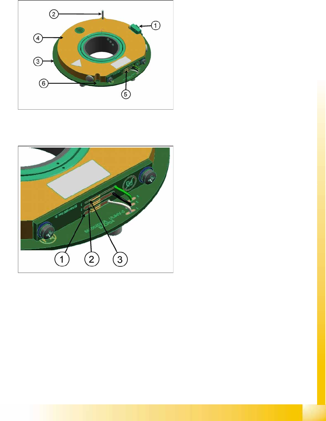
C&P20A Head – E/D Transformer (Collector Ring)
Energy transmission
7-3: E/D transformer
The E/D transformer consists of a stationary
and a rotating part.
The three sliding contacts (5) transmit the
direct current voltage (24V/4A).
Communication, in other words the
transmission of CAN Bus signals, is
contactless.
Connector (1) (connection to intermediate
distributor)
The centering pin (2) fixes the stationary part
(4) in place.
The rotating part (3) is fixed with five screws to
the star carrier. These can be loosened via the
service opening (6).
7-4: E/D transformer – energy transmission
Two transmission leads are needed to
transmit the energy supply:
P24V (1) and GND (2).
Another lead (sliding contact) forms the
connection between the rotating part and the
housing ground (ESD protection (3)).