00196044-05 - sg x und x4i fse_en.pdf - 第240页
C&P20A Overview Parts Overview with Function Description S tudent Guide (FSE) SI PL ACE X Series and X4I C&P20A Edition 01/2009 EN 240 7.2.3.1 Pressure Control V alve C&P20A function units Pressure Control V …
C&P20A
Parts Overview with Function Description Overview
Student Guide (FSE) SIPLACE X Series and X4I
Edition 01/2009 EN C&P20A
239
Advantages compared with DLM heads
The holding circuit has one venturi nozzle for each segment: No more interference between the
segments.
No vacuum plunger: Digital pressure control valve: Faster switching times between vacuum and air
blast.
The placement star is now positioned at an angle this lead to a compact space for arranging the 20
segments and integrating the component camera into the head.
Lower inlet pressure: Lower air consumption per segment.
Autonomous rotation and positioning of each segment: Increases placement performance.
No swiveling in and out of DP station onto the segment: Greater accuracy and robustness.
Component sensor in the pickup/placement position: Greater placement reliability.
Digital camera interface: Faster image evaluation
Linear motor with Z drive : reduction of moving mass this increases placement capacity.
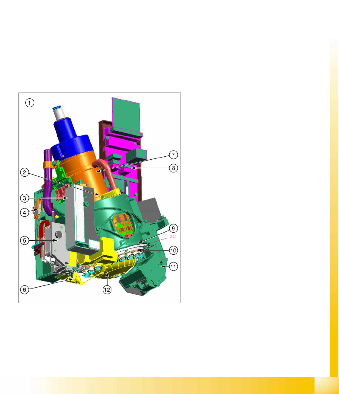
7.2.3 Parts Overview with Function Description
7-2: C&P20A parts
This chapter describes the main parts of the
C&P20A head and their technical function.
The description is ordered according to the
sequence of disassembly for servicing.
Legend
1. C&P20A assembly
2. E/D transformer
3. Vacuum generator (Placement/Pick up circuit)
4. Pneumatic return unit
5. Z drive
6. Component sensor
7. Star motor
8. Intermediate distributor board
9. Raceway
10. DP drive
11. Component Camera
12. Silencer holding circuit
C&P20A
Overview Parts Overview with Function Description
Student Guide (FSE) SIPLACE X Series and X4I
C&P20A Edition 01/2009 EN
240
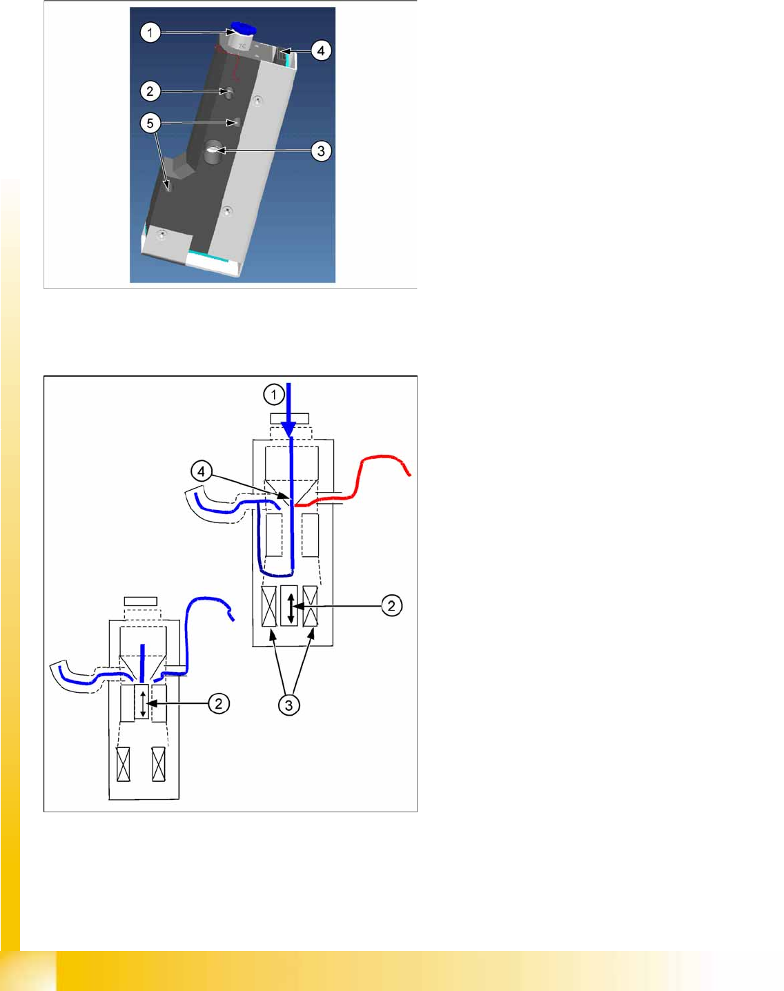
7.2.3.1 Pressure Control Valve
C&P20A function units
Pressure Control Valve - Function
Pressure control valve (digital)
The pressure control valve supplies the
pickup/placement circuit with vacuum during
the pickup process and switches over to air
blast during placement.
This valve is fixed to the placement head with
two screws and can be replaced during
service work.
Legend
1. Compressed air connection
2. Vacuum/air blast for pickup/placement circuit
3. Discharged air, for cooling the X linear motor
4. Energy and data supply
5. Pressure control valve fixture
Legend
1. Compressed air
2. Pistons
3. Motor
4. Venturi nozzle
After initialization, the piston is in a central
position, in which neither vacuum nor air blast
is applied to the nozzle.
During pickup, the piston is always in the open
position, in which maximum vacuum is
produced and applied to the nozzle.
The function
Early vacuum
should always be
switched on for the C&P20A head. However, if
this function is switched off, the piston will be
in the "open position". The vacuum will only be
switched on again after the "light barrier down"
signal has been issued . -> 2 additional
switching steps -> time loss.
C&P20A
Parts Overview with Function Description Overview
Student Guide (FSE) SIPLACE X Series and X4I
Edition 01/2009 EN C&P20A
241
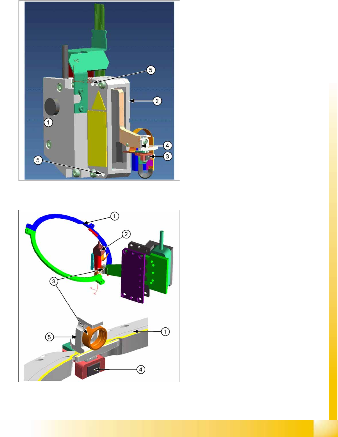
7.2.3.2 Z axis
Z Drive Function
Legend
1. Incremental measurement system, resolution
0.5 µm
2. Linear motor, primary part, moves up and
down between the secondary parts.
3. Light barrier Z-down emits the end position
signal for the Z axis.
4. Snap jaws: The ball bearing for the DP drive is
rotated via the star axis into the jaw, allowing
the segment to be moved upwards and
downwards.
5. Z axis fixtures
The Z axis and return unit are fixed to the head as
a complete unit, with two screws, and can be
easily replaced during service work.
Legend
1. Raceway
2. Segment
3. Ball bearings
4. Light barrier down
5. Snap jaws
The jaws are installed on the primary part of
the Z motor, for mechanical docking of the
segments.
A Z down sensor is located in the placement
position, for recognition of the Z axis put down
position. This recognizes a relative movement
between the nozzle and DP segment. When
the Z axis springs into place, this sensor sends
a signal to the axis controller board. The "light
barrier down" signal is directly linked to the
measurement signal of the Z axis incremental
encoder.