00196044-05 - sg x und x4i fse_en.pdf - 第603页
MTC2 Factory settings Masterdrives S tudent Guide (FSE) SIPL ACE X Series and X4I Edition 01/2009 EN MTC2 607 U501 = Mac hine data P060 = Function parameters for selection of curr ent menu Index 4: Addres s P095 = …
MTC2
Masterdrives Operating the master drive with the parametrization unit (PMU)
Student Guide (FSE) SIPLACE X Series and X4I
MTC2 Edition 01/2009 EN
606
14.4 Masterdrives
14.4.1 Operating the master drive with the parametrization unit (PMU)
14.4.2 Important Parameter for trouble shooting
U / r = visualization parameters
P = parameters which can be changed
r004 = Output current inverter, converter
r006 = Actual DC intermediate circuit voltage
r009 = Temperature motor
r069 = Software version
Index 1 Masterdrives
Index 2 Option BG Slot A
Index 3 Option BG Slot B
Index 4 Option BG Slot C
U003 = Parameter set version:
For the feed axis of tower 1/2 software version
For the lifting axis of tower 1/2 software version
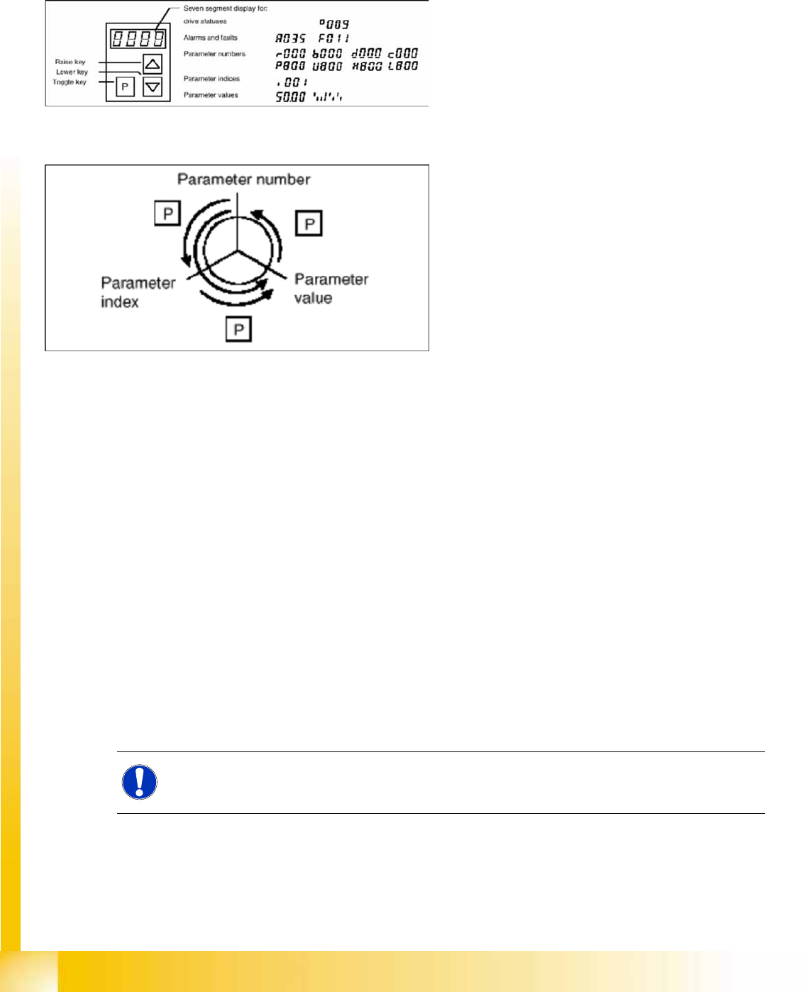
14-63: PMU parameterizing unit
The PMU parameterizing unit enables
parameterization, operator control and
visualization of the converters and inverters
directly on the unit itself.
14-64: Toggle key of the PMU
With the toggle key, you can change over:
from the parameter number to the parameter
index
from the parameter index to the parameter
value
from the parameter value to the parameter
number
If the parameter is not indexed, you can jump
directly from the parameter number to the
parameter value.
NOTE:
The MTC2 parameter sets differ from one another, due to the mechanical construction.

MTC2
Factory settings Masterdrives
Student Guide (FSE) SIPLACE X Series and X4I
Edition 01/2009 EN MTC2
607
U501 = Machine data
P060 = Function parameters for selection of current menu
Index 4: Address
P095 = Motor list with standard motors
P096 =Function parameter motor
Define serial Interface:
P700 interface address of COM 1
P701 baud rate 8 is equal to 38400
14.4.3 Factory settings
Reset the Master drives to the define defaults
You must change 3 Parameters to define the defaults
after this you can download the parameter set for the axis.
Change parameter P053 from 7 to 6 (this value is a binary code 0111 --> 0110).
Set Parameter P060 from 7 to 2.
Change Parameter P970 from 1 to 0. Parameter-Reset is started.
Check the serial interface and CAN Bus address after RESET:
Adjust the V24 (RS232) Interface.
– Parameter P700 = 0
– Parameter P701 --> index 1 = 8 (= baud rate 38400).
Check the address for Can -Bus Parameter P918.
Download the Parameter set for the Axis with the Laptop.
ATTENTION:
When setting factory defaults, the axis concerned must not be subject to position control.
MTC2
Masterdrives Setting the CAN bus address at the master drive PMU
Student Guide (FSE) SIPLACE X Series and X4I
MTC2 Edition 01/2009 EN
608
14.4.4 Setting the CAN bus address at the master drive PMU
It is necessary to enter the addresses of the feed and lifting axes on the PMU’s (Parameterization Units)
for the Master drives on initial commissioning of the MTC and after the replacement of the Master drives.
This can be performed external to the MTC. The Master drives must be supplied with 24 V DC. The
control for the related axis must be shut down.
These brief instructions show how to enter the address for the Masterdrive of the lifting axis for tower 1.
For more detailed information, see the chapter "Parameterization" in the user manual for "SIMOVERT
MASTERDRIVES".
The following addresses are provided for the lifting and feed axes:
X Select , to go to the parameter numbers.
X Step with , until you reach the seven segment number
P060
. This is the menu selection.
X Select . A number will appear on the display. This is the
Parameter menu
.
X Step with , until you reach the number
4
. ("4" means "module configuration").
X Select . You will see
004
on the display. This is the status indicator for
Module configuration
.
X Select , to go to the parameter numbers. You will see
P060
.
X Step with , until you reach the seven segment number
P918
. This is the parameter number for
the bus address.
NOTE:
For setting the CAN Bus address you could use the software "Drive Monitor". For manual
adjustment of the CAN bus address, see Section (14.3 MTC2 Calibration and Settings
J
571 ) .
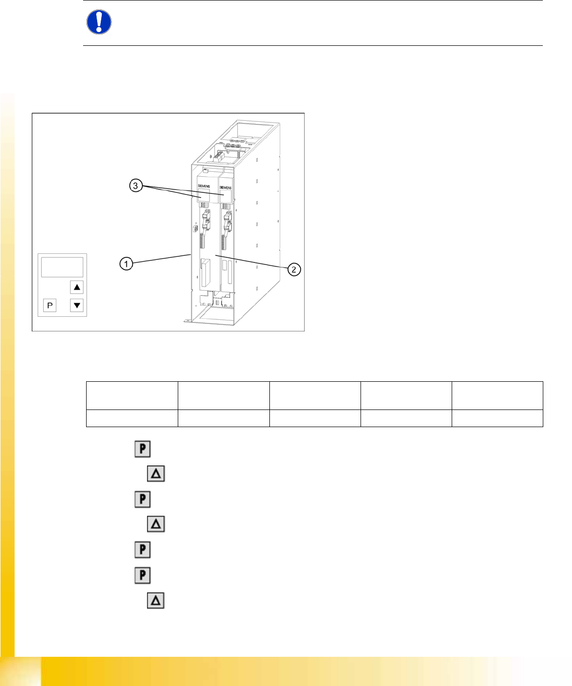
14-65: Masterdrives of the lifting and feed axes (shown here for tower 1)
Legend:
1. Masterdrive of the lifting axis for tower 1
2. Masterdrive of the feed axis for tower 1
3. Masterdrive of the lifting axis for tower 2
4. Masterdrive of the feed axis for tower 2
5. Control panels
Lifting axis 1
(PMU 1)
Feed axis 1
(PMU 2)
Lifting axis 2
(PMU 3)
Feed axis 2
(PMU 4)
Address 1234