00196044-05 - sg x und x4i fse_en.pdf - 第570页
MTC2 MTC2 Calibration and Settings SITEST Calibration Flow Charts S tudent Guide (FSE) SI PL ACE X Series and X4I MTC2 Edition 01/2009 EN 574 14.3.2 SITEST Calibr ation Flow Chart s 14.3.2.1 Lif ting axis 14-36: Overview…
MTC2
Calibration sequence in general MTC2 Calibration and Settings
Student Guide (FSE) SIPLACE X Series and X4I
Edition 01/2009 EN MTC2
573
14.3.1.2 Terms of calibration feed axes
Zero offset (zero position)
The zero offset is used to define the removal position of WTC 1. The zero offset is the difference
between the physical home position of the feed axis and the position of the driver at which it is
inserted in the WTC on level 1.
Removal positions (WTC removal positions)
At the removal positions of WTC 1 - 5 (tower 2: WTCs 1 - 4), the driver can be inserted into the lowest
WTC in each cassette and move this into the transfer position.
Transfer position (component transfer position)
The transfer position is the position of the feed axis at which components can be picked up by the
placement head of the SIPLACE station without a correction value. The position of the waffle pack
tray reference edges in relation to the reference holes of the MTC2 is stored in the line computer.
min. and max. position
The end positions of an axis are reached when contact is made with the relevant limit switch. The
value determined here is used as a safety constraint when values are entered in the service menu
of the controller software. If a limit switch is overrun during operation, the relevant axis is stopped
immediately to prevent a crash from occurring.
Handle sensor, WTC safety query and crash light barriers
The handle sensor checks the handle of the WTC in the removal position and thus the position of
the WTC which has been moved back, to prevent a crash from occurring.
The WTC safety query checks the correct position of the WTC which has been moved back before
the lifting axis is moved, to prevent a crash from occurring.
Depending on the height of the waffle pack tray which has been set up, the crash light barriers check
the height of the WTC which is moving back, to prevent a crash from occurring in the cassette.
Disengaging mechanism
The disengaging mechanism enables the driver to engage with and disengage from the WTC.
CAUTION:
Incorrectly set machine data can result in a crash between the lifting and feed axes or at the limit
positions of these axes.
NOTE:
For calibrating the zero point correction and transfer position at the feed axis, read the notes in
Section (14.3.2.2 Feed axis
J
575 ) .
MTC2
MTC2 Calibration and Settings SITEST Calibration Flow Charts
Student Guide (FSE) SIPLACE X Series and X4I
MTC2 Edition 01/2009 EN
574
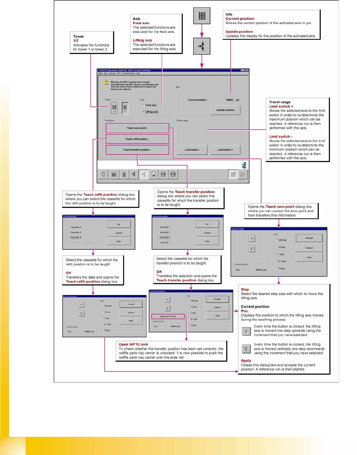
14.3.2 SITEST Calibration Flow Charts
14.3.2.1 Lifting axis
14-36: Overview "Calibration Lifting axes"
MTC2
SITEST Calibration Flow Charts MTC2 Calibration and Settings
Student Guide (FSE) SIPLACE X Series and X4I
Edition 01/2009 EN MTC2
575
14.3.2.2 Feed axis
Notes for calibration the zeropoint correction and transfer position into the machine.
1a. Calibration of zero point correction:
X Select
SITEST
-->
MTC
-->
Settings
X Select
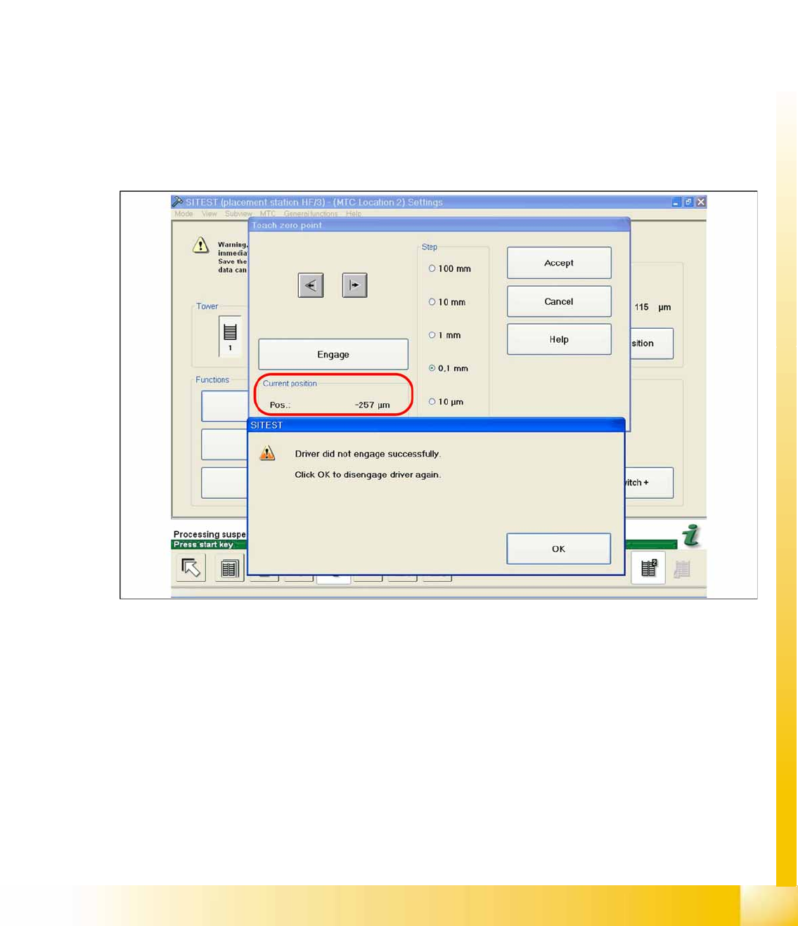
Teach zero point.
X Check the position of the driver with the
ENGAGE
.
In case the driver did not engaged successfully you must determine the middle of the notch of the waffel
pack tray.
The accurate adjustment is described below:
X If the feed axis is positioned so that the driver is unable to connect, move the feed axis into an
approximately correct position, in which the driver is able to engage. Now determine the minimum
and maximum position in which the driver can engage.
X Once the driver has engaged, gently tap the feed axis into the minimum position, until the driver is
just unable to engage (see diagram).
X Make a note of the position value shown.
14-37: Minimum position
X Now gently tap the feed axis into the maximum position, until the driver is just unable to engage (see
diagram).