00196044-05 - sg x und x4i fse_en.pdf - 第556页
MTC2 Construction and mode of operation Modules of the contro ller S tudent Guide (FSE) SI PL ACE X Series and X4I MTC2 Edition 01/2009 EN 560 Terminal strips: – X01 feed-in – X02 24 V voltage supply for sensors/actu a…

MTC2
Modules of the controller Construction and mode of operation
Student Guide (FSE) SIPLACE X Series and X4I
Edition 01/2009 EN MTC2
559
Two CAN bus interfaces (maximum transfer rate: 1 MBaud/s)
CAN1: Communication with the SIPLACE station
CAN2: Control of the 4 Masterdrives
Power supply: 24 VDC
Power consumption: 500 mA
24 inputs via a 37-pole Sub-D connector for the sensors
8 inputs via a 15-pole Sub-D connector for the actuators;
The outputs are short-circuit proof;
Current per output: 0.7 A, briefly up to 2.5A
14.2.5.2 Masterdrives
The Masterdrives are controlled via the internal CAN bus system between microcontroller and
masterdrive.
Controlling the holding brakes for the lifting axes
Controlling the braking resistors of the lifting axes
Controlling the permanently excited synchronous motors of the lifting and feed axes
Evaluating the resolver
14.2.5.3 24V power supply
The 24V power supply supplies:
The C167 controller board
The logic circuitry of the Masterdrives
The sensors and the actuators
14.2.5.4 Electronics board
Electronics board with the following components:
Main switch: S01
EMERGENCY STOP button: S15
Automatic circuit breakers:
– F00 main fuse
– F01 24 V sensors 1
– F02 24 V sensors 2, master drive control voltage
Motor protection swtich: Q01 Masterdrives
Contactors:
– K01.1 master drive lifting axis tower 1
– K01.2 master drive feed axis tower 1
– K02.1 master drive lifting axis tower 2
– K02.2 master drive feed axis tower 2
Optocouplers:
– U09 brake tower 1
– U06 brake tower 2
MTC2
Construction and mode of operation Modules of the controller
Student Guide (FSE) SIPLACE X Series and X4I
MTC2 Edition 01/2009 EN
560
Terminal strips:
– X01 feed-in
– X02 24 V voltage supply for sensors/actuators
– X03 emergency stop circuit
– X04 sensors/actuators tower 1
– X05 sensors/actuators tower 2
– X06 sensors/actuators
14.2.5.5 Mounting plate
A mounting plate with the following components:
Combination circuit breakers: K03 - K05
Braking resistor: R01
Braking resistor: R02
Power supply, 24 V DC: T01
Line filter: Z01
Discharge reactor (Is this part missing in your MTC please order the retrofitting kit 03016518-01, that
for your own safety.)
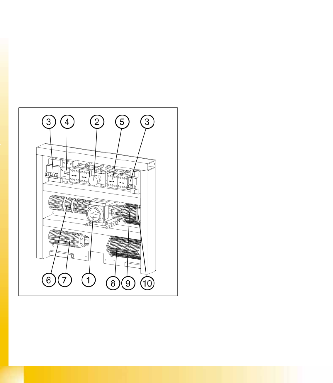
14-25: Electronics board and mounting plate 1
Legend
1. Main switch
2. EMERGENCY STOP button
3. Automatic circuit breakers
4. Motor Circuit Breaker
5. Contactors
6. Grounding terminals
7. Through terminals
8. Initiator LED terminals
9. Actuator LED terminals
10. Optocouplers
MTC2
Modules of the controller Construction and mode of operation
Student Guide (FSE) SIPLACE X Series and X4I
Edition 01/2009 EN MTC2
561
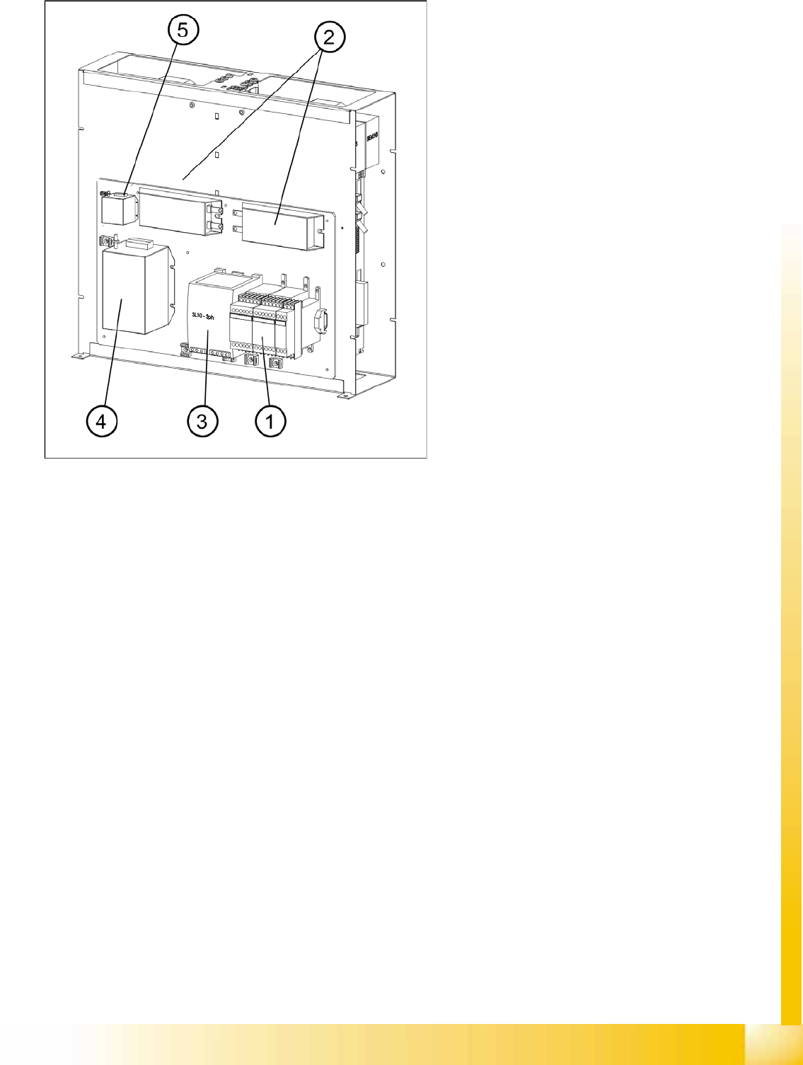
14-26: Electronics board and mounting plate 2
Legend
1 Combination circuit breakers
2 Braking resistors
3 Power supply
4 Line filters
5 Discharge reactor