00196044-05 - sg x und x4i fse_en.pdf - 第189页
Energy and Compressed Air Supply Safety and Signaling Circuit Power supply S tudent Guide (FSE) SIPL ACE X Series and X4I Edition 01/2009 EN Energy and Compressed Air Supply 189 Stop Button Loo p 5-17: Stop Button Loop T…
Energy and Compressed Air Supply
Power supply Safety and Signaling Circuit
Student Guide (FSE) SIPLACE X Series and X4I
Energy and Compressed Air Supply Edition 01/2009 EN
188
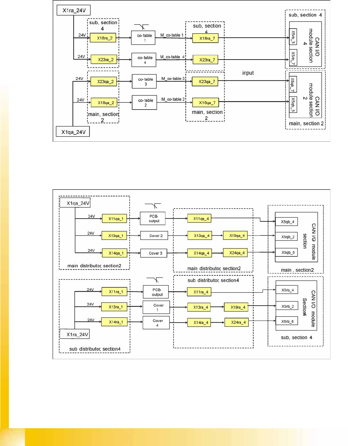
5.2.8.2 Control Loops
Changeover Table Loop
5-15: Changeover table loop
The 4 component tables are switched in parallel mode. If one or more tables are not connected, the
contact will close and 24 V will be present at the input of the CAN I/O module in sector 2 or 4.
Cover Control Loop
5-16: Cover Control Loop
The cover control loop consists of 6 contacts (2 main covers, each with 2 contacts and 2 covers on the
conveyors (input and output)), which are switched in parallel mode. If 1 or more covers are open, the
contact will close and the 24 V will be present at the input of the CAN I/O module in sector 4. The same
applies to sector 2. This shows that one of the covers is open.
Energy and Compressed Air Supply
Safety and Signaling Circuit Power supply
Student Guide (FSE) SIPLACE X Series and X4I
Edition 01/2009 EN Energy and Compressed Air Supply
189
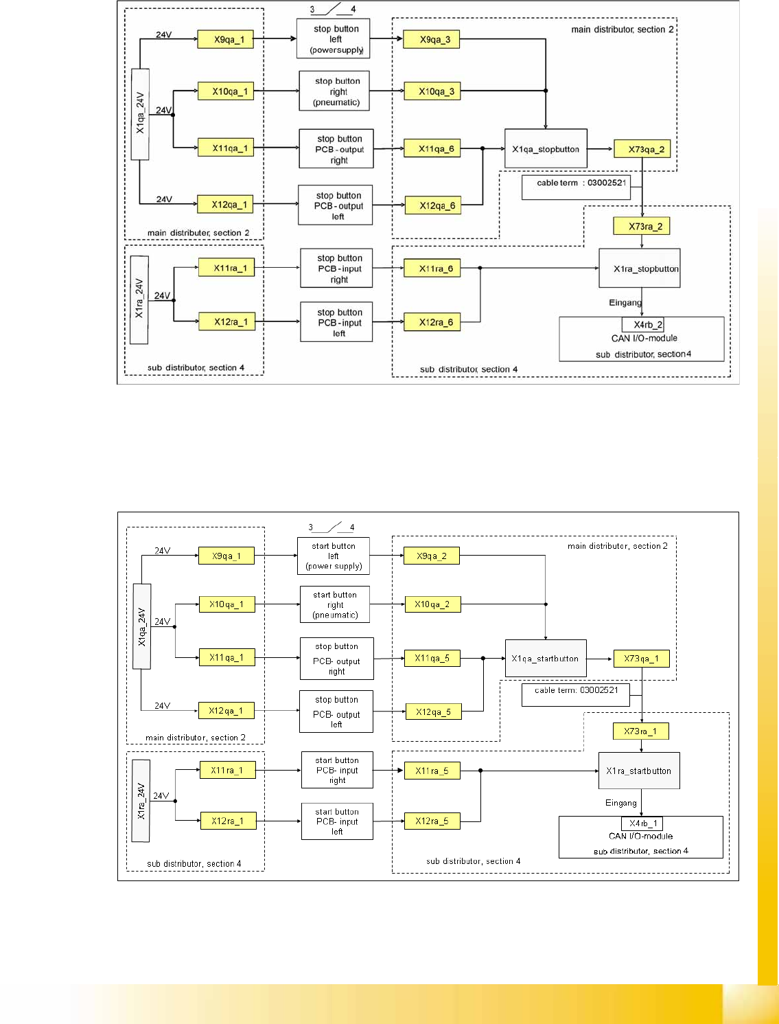
Stop Button Loop
5-17: Stop Button Loop
The stop button loop consists of 6 contacts which are switched in parallel mode. If one or more STOP
buttons has been pressed, the contact will close and 24 V will be present at the input of the CAN I/O
module in sector 4, showing that one of the STOP buttons has been pressed.
Start Button Loop
5-18: Start Button Loop
The start button loop consists of 6 contacts and they are switched in parallel mode. If one or more START
buttons has been pressed, the contact will close and the 24 V will be present at the input of the CAN I/
O module in sector 4, showing that one of the START buttons has been pressed.

Energy and Compressed Air Supply
Power supply Safety and Signaling Circuit
Student Guide (FSE) SIPLACE X Series and X4I
Energy and Compressed Air Supply Edition 01/2009 EN
190
5.2.8.3 How Does the Emergency STOP Circuit Function?
The placement system cannot be used in placement mode until all the supply voltages have been
enabled by the protective contactor combination.
The following conditions must also be fulfilled:
All four component changeover tables must be docked.
All covers must be closed.
Both emergency stop buttons must be released.
The minimum air pressure must be present.
The software enable signal must be ready.
The message
Safety loop OK
Must be sent (for GND on X6 on SSK, CAN I/O output)
24 V must be present at the START button.
After pressing the start button, the protective contactor combination releases the following voltages:
Secondary circuit 250 V for servo X/Y axis (via K2, K3, K4).
Secondary circuit 150 V for star axis.
The servo unit receives
the servo release signal
for the servo amplifier (K4.5)
The message
Ctrl_On
must be issued at CAN I/O (24 V from the axis unit after receiving
the servo
release signal
)
34 V operating voltage for the transport handling.
24 V operating voltage for the tape cutter.
M_X/Y: +24 V for K3 and K4
M_tape cutter: +24 V for K2