00196044-05 - sg x und x4i fse_en.pdf - 第42页
Operational Safety Safety Features Switches and Buttons on the Placement Machine S tudent Guide (FSE) SI PL ACE X Series and X4I Operational Safety Edition 01/2009 EN 42 2.4.1.2 Position of protective switches on the pla…
Operational Safety
Switches and Buttons on the Placement Machine Safety Features
Student Guide (FSE) SIPLACE X Series and X4I
Edition 01/2009 EN Operational Safety
41
2.4 Safety Features
2.4.1 Switches and Buttons on the Placement Machine
2.4.1.1 Position of Switches and Buttons on the Placement Machine
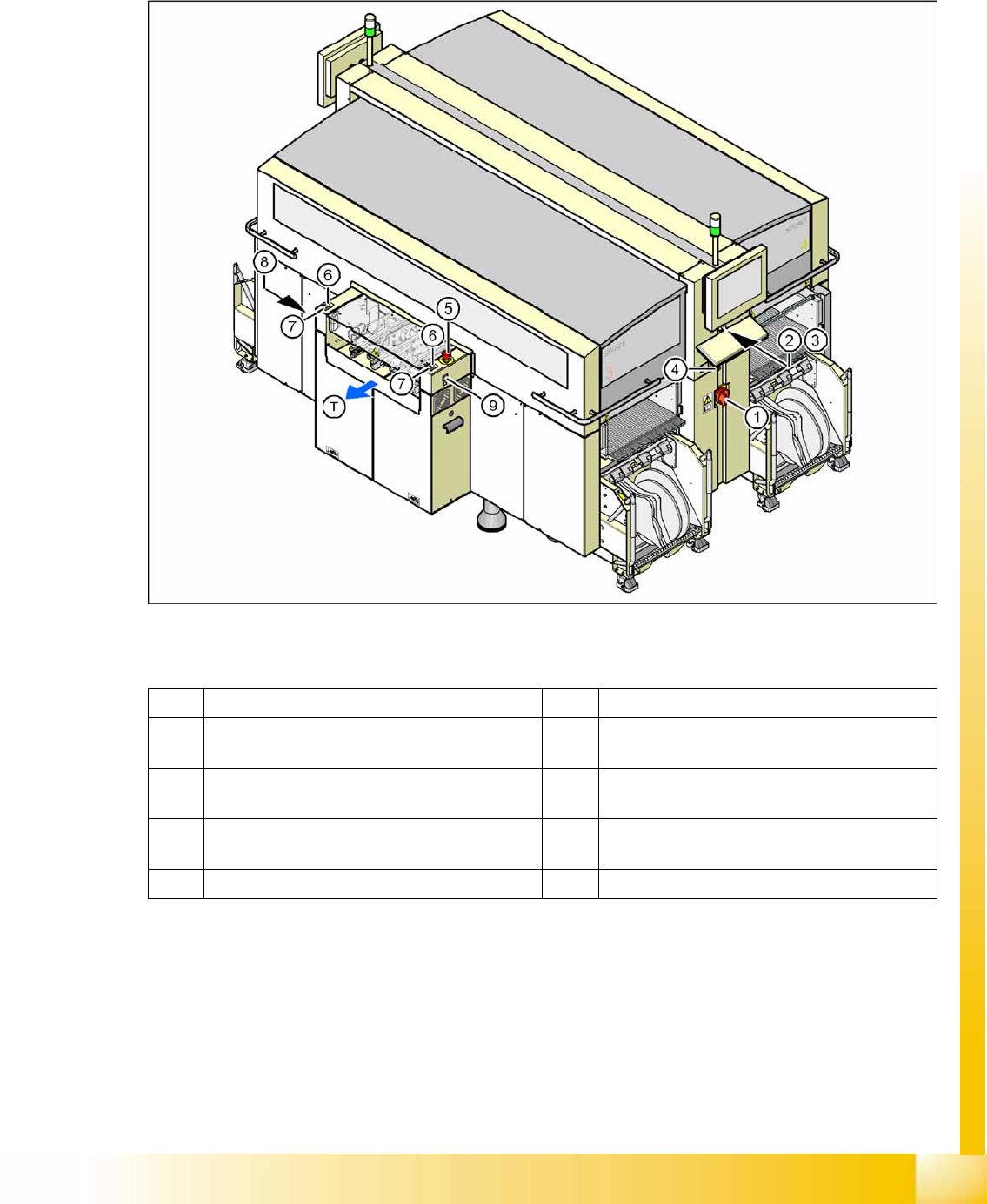
2-17: Position of switches and buttons - View of the PCB output side
Legend
1 Main switch 6 Start button (white) on the output side
2 Stop button (black) on the operator panel on the
power supply side
7 Stop button (white) on the output side
3 Start button (white) on the operator panel on the
power supply side
8 Button (black) for docking and undocking the
component trolley, location 2
4 Component counter on the operator panel on
the power supply side
9 Button (black) for docking and undocking the
component trolley, location 3
5 Emergency stop button on the output side T PCB transport direction
Operational Safety
Safety Features Switches and Buttons on the Placement Machine
Student Guide (FSE) SIPLACE X Series and X4I
Operational Safety Edition 01/2009 EN
42
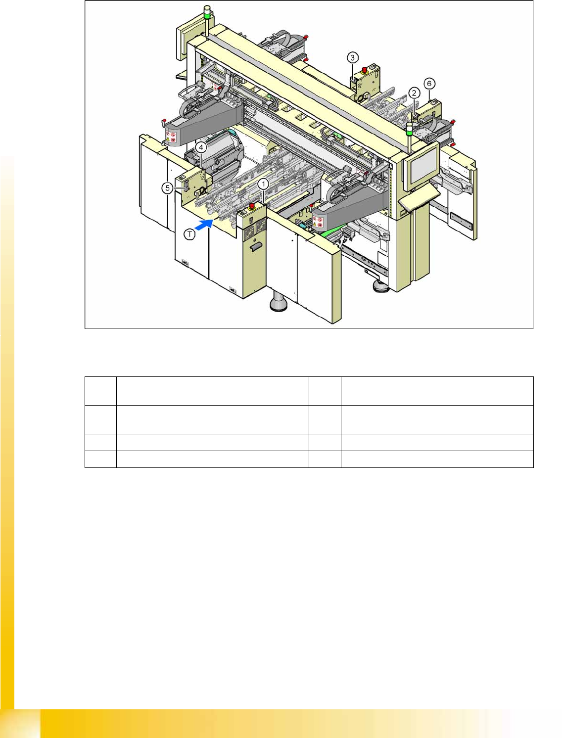
2.4.1.2 Position of protective switches on the placement machine
2-18: Position of protective switches on the placement machine
Legend
1 Protective cover switch, location 1 5 Protective switch for the cover flap on the PCB
conveyor input side
2 Protective cover switch, location 2 6 Protective switch for the cover flap on the PCB
conveyor output side
3 Protective cover switch, location 3 T PCB transport direction
4 Protective cover switch, location 4
Operational Safety
Switches and Buttons on the Placement Machine Safety Features
Student Guide (FSE) SIPLACE X Series and X4I
Edition 01/2009 EN Operational Safety
43
2.4.1.3 Function Description
Main power switch in the OFF position
The main power switch disconnects the three phases L1, L2, and L3 from the power supply.
Cable connection terminals L1, L2, and L3 of the Q1 main power switch
Z1 line filter
Service socket X102
F1 automatic circuit breaker for the service socket
The color of all individual wires, which still carry potentially lethal voltages even if the main power
switch is switched off, is brown.
– Death, serious injury or considerable damage may result if these automatic placement systems
are handled incorrectly.
– Always follow the applicable accident prevention and DIN regulations (particularly DIN EN 60
204, part 1) and the applicable regulations in your own country.
– The safety door to the power supply must ONLY be opened by appropriately qualified and
trained personnel.
EMERGENCY STOP pushbutton, latching, with override protection to EN 418
The emergency stop button is red and latches in the ON position when pressed. When you press the
emergency stop button, the switching contact of the emergency stop circuit opens and the protective
contactor combination (SSK K6) trips. The intermediate circuit voltage (250 VDC) for the gantry axes and
the intermediate circuit voltage (145 VDC) for the star axes is switched off. The servo amplifiers for the
DP and Z axes are still supplied with 40 VDC. The signaling contact of the EMERGENCY STOP button
will open and the message
EMERGENCY STOP operated
will be shown on the screen. The following
assemblies will be disabled:
PCB conveyor
PCB clamping
Width Adjustment
PCB stopper
Empty tape cutter.
See also:
J
2.4.3.1 Safety Circuit Function [
J
45]
DANGER:
The following components still carry potentially lethal voltages even if the main power switch is
switched off:
NOTE:
Placement will be interrupted and can then be continued or canceled once the machine is
functional again.