00196044-05 - sg x und x4i fse_en.pdf - 第120页
Communication and Control CAN Bus X Feeder - Communication S tudent Guide (FSE) SI PL ACE X Series and X4I Communication and Control Edition 01/2009 EN 120 4.3.9 X Feeder - Communication 4-28: Communication X feeder The …
Communication and Control
Communication CPP Head CAN Bus
Student Guide (FSE) SIPLACE X Series and X4I
Edition 01/2009 EN Communication and Control
119
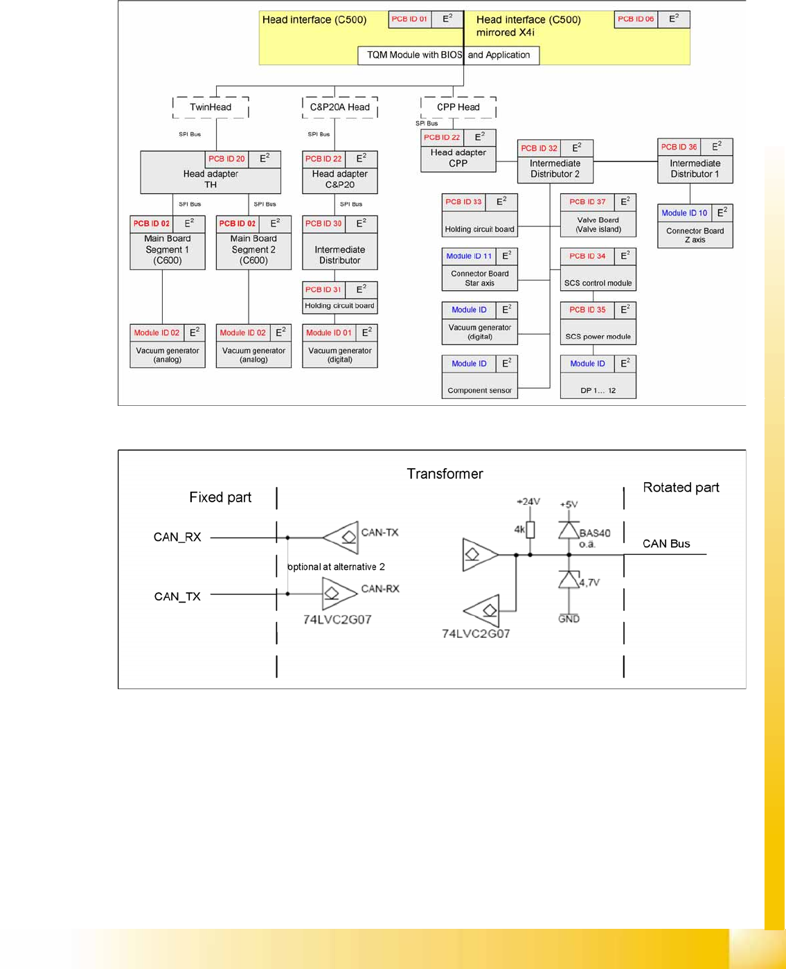
4.3.8.3 EEPROMs on CPP Head
EEPROMs are present on all boards (except E/D transformer). Various data are stored there, according
to the individual functions e.g. production date, material number, zero point correction values, offset
values, plus operating and statistical data.
4.3.8.4 Data Transfer
The communication with the DP drives (CAN bus) is contactless via a transmitter unit (on the back
cover of the CPP head) and a receiver unit (on the valve terminal).
This communication is via 2 channels, whereby channel 1 is responsible for supplying data to the
DP drives and channel 2 is responsible for communication to the Z down light barrier of the axis card
(HCU).
The head CAN bus is – in this case – not used as a differential CAN bus with the CAN_L and CAN_H
signals but as a 1 wire CAN on the rotor.
Communication and Control
CAN Bus X Feeder - Communication
Student Guide (FSE) SIPLACE X Series and X4I
Communication and Control Edition 01/2009 EN
120
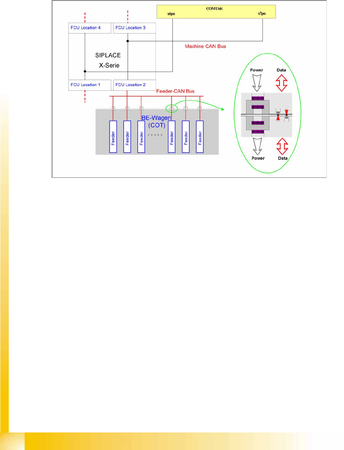
4.3.9 X Feeder - Communication
4-28: Communication X feeder
The communication between the Feeder Control Unit (FCU) and each X feeder is carried out via a CAN
bus. This CAN bus is only responsible for the communication between the FCU and the feeders and is
controlled by the machine CAN bus.
The data and power supply from the FCU to each feeder is contactless.
Communication and Control
CAN I/O Module (SLIO) SIPLACE X CAN Bus
Student Guide (FSE) SIPLACE X Series and X4I
Edition 01/2009 EN Communication and Control
121
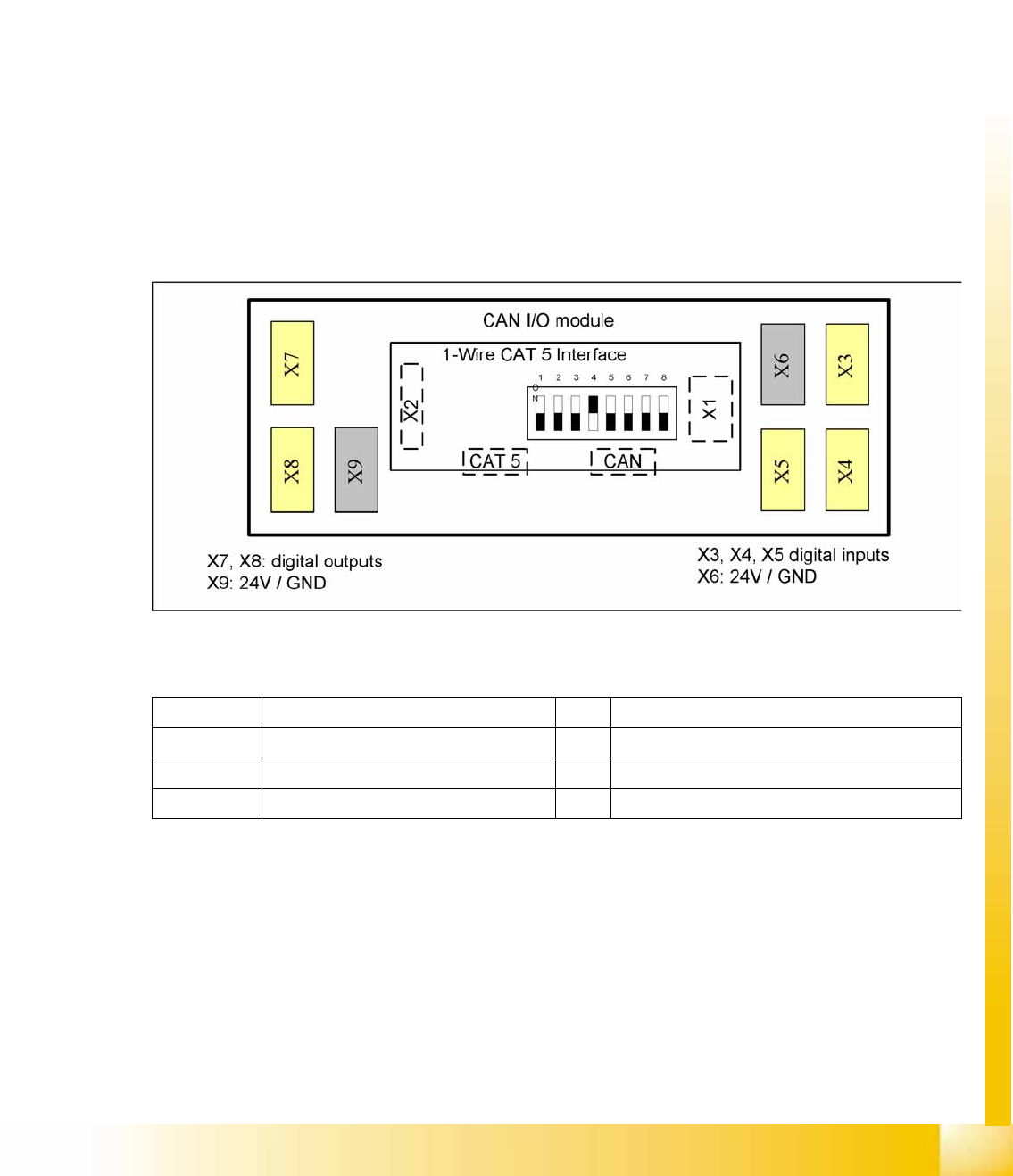
4.3.10 CAN I/O Module (SLIO) SIPLACE X
SIPLACE X machines use 2 CAN I/O modules. Both modules are absolutely identical and are located in
sectors 2 (main distributor) and 4 (subdistributor). The introduction of the one wire bus system means
that there is now an additional board plugged into the I/O module (Interface 1-Wire CAT5).
Product characteristics:
Micro controller with integrated CAN controller
Data memory
Program memory (flash)
CAN interface with 9 pin connector and address alignment
16 digital Output 24 V with status LED
24 digital Input 24 V with status LED
Download interface
Power supply 24V
The 8 digital inputs can be logically linked with the help of a FPGA (freely programmable gate array).
The FPGA is used for incoming security messages.
4-29: Example: Subdistributor
Legend
The jumper on the rear side activates the RS232 interface for service purposes.
X1 CAN Bus Interface to I/O module X2 RS232 interface
X3, X4, X5 Digital inputs 24V X6 24 V / GND
X7, X8 Digital outputs 24V X9 24 V / GND
CAT5 Interface 1-Wire connector CAT5 cable CAN CAN bus connector